
Sensors and methods and apparatus relating to same
a technology of sensors and methods, applied in the direction of positive displacement liquid engines, instruments, machines/engines, etc., can solve the problems of mechanical failure, mechanical failure, and inclined to experience mechanical failure, so as to affect the ability of capacitors, sensor and/or pump control, and accurately measure capacitance.
- Summary
- Abstract
- Description
- Claims
- Application Information
AI Technical Summary
Benefits of technology
Problems solved by technology
Method used
Image

Examples
Embodiment Construction
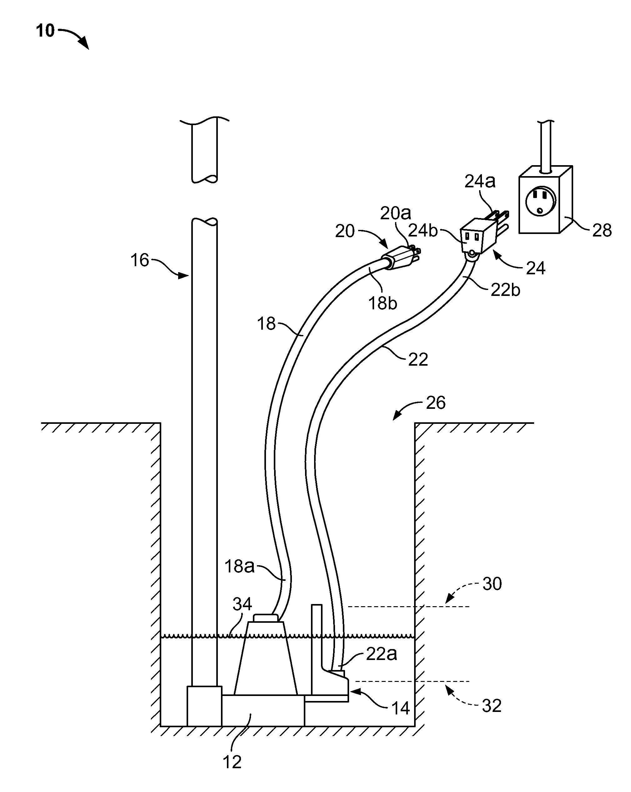
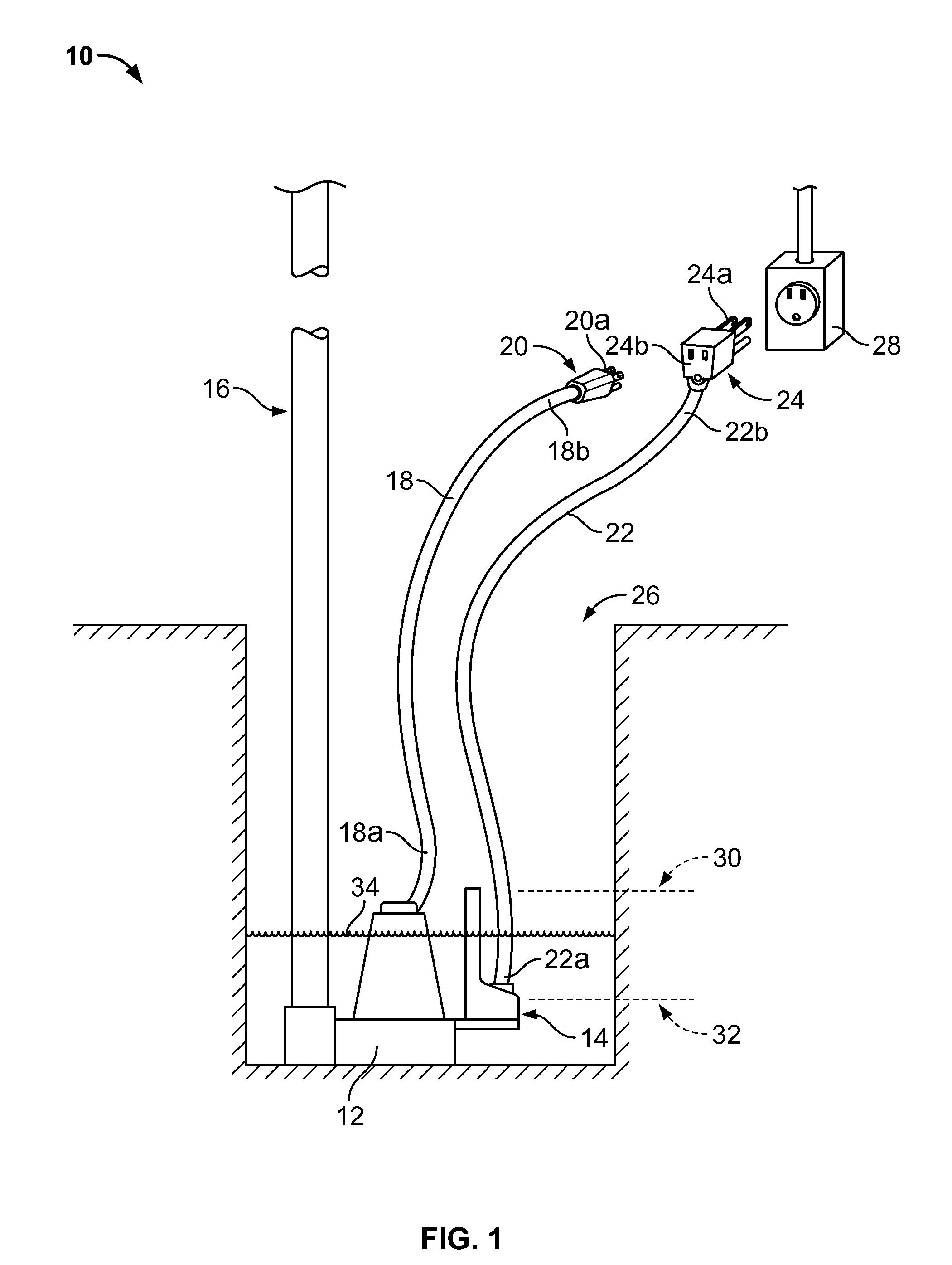
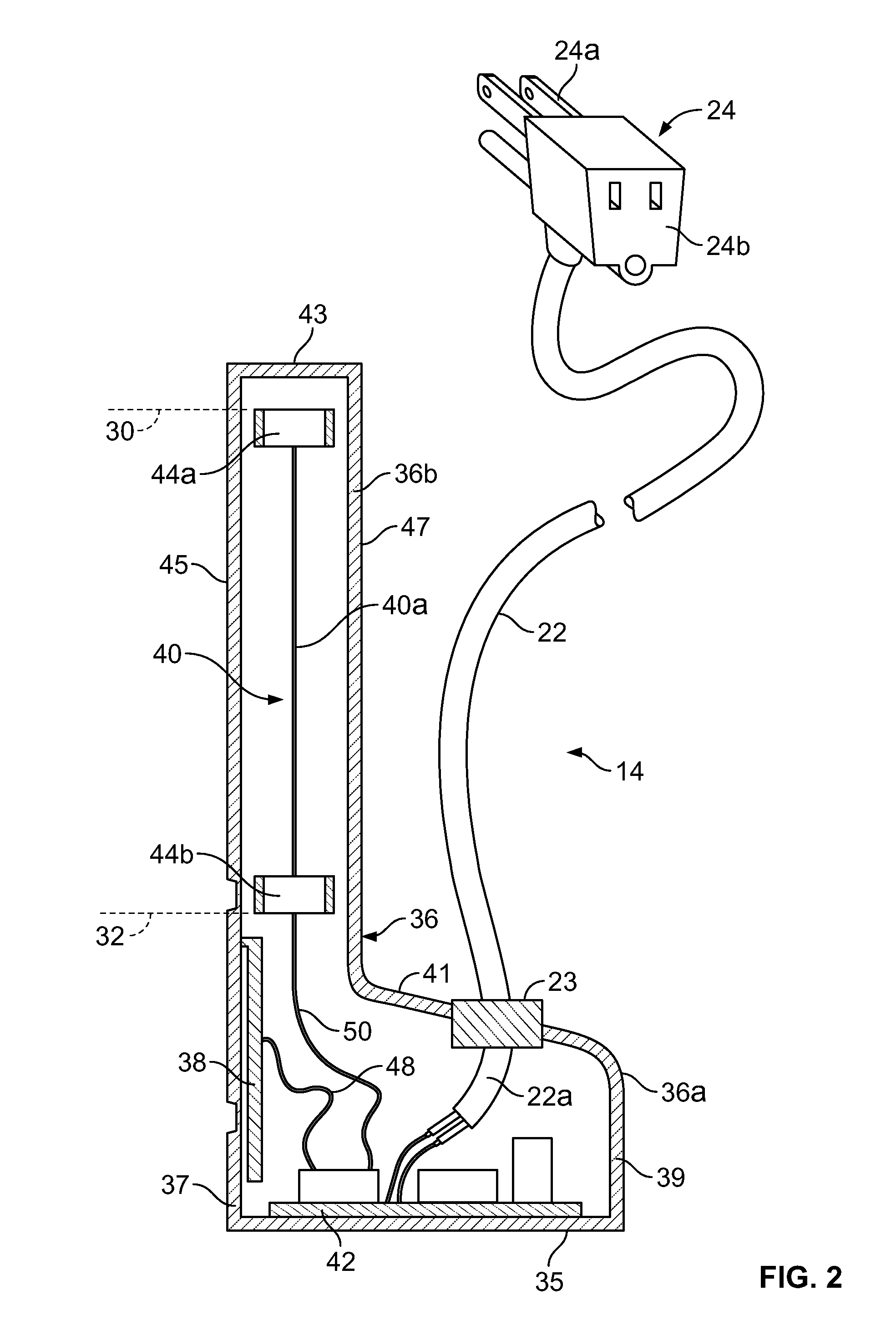
FIG. 1 depicts a sump pump system 10 disposed within a reservoir 26. The sump pump system 10 includes a pump 12, a sensor or sensor unit 14, and a discharge pipe 16. In general, the sensor unit 14 monitors the level of a liquid 34 within the reservoir 26 and serves as a switch for activating and deactivating the pump 12 based on that level. When the level of the liquid 34 reaches a predetermined upper limit, which is identified by reference numeral 30 in FIG. 1, the sensor unit 14 activates the pump 12. Upon activation, the pump 12 begins moving the liquid 34 up and out of the reservoir 26 via the discharge pipe 16. This begins to lower the level of the liquid 34 in the reservoir 26. Once the level of the liquid 34 reaches a predetermined lower limit, which is identified by reference numeral 32 in FIG. 1, the sensor unit 14 deactivates the pump 12. The details of the sump pump system 10 will now be discussed in more detail with continued reference to the figures.
FIG. 1 depicts the s...
PUM
 Abstract
Description
Claims
Application Information