Sensors and methods and apparatus relating to same

a technology of sensors and methods, applied in the direction of positive displacement liquid engines, instruments, liquid fuel engines, etc., can solve the problems of mechanical failure, mechanical failure, and inability to accurately measure capacitance, so as to reduce the risk of mineral buildup, accurately measure capacitance, and affect the ability of capacitors, sensor and/or pump control

Inactive Publication Date: 2011-05-12
MAYLEBEN PHILIP +2
View PDF99 Cites 79 Cited by
  • Summary
  • Abstract
  • Description
  • Claims
  • Application Information

AI Technical Summary

Benefits of technology

[0013]One advantage of this form of the present invention is that it requires no moving parts that may suffer mechanical failure. The apparatus serves as a solid state sensor that detects liquid level to control activation and deactivation of the pump. Another advantage of this form of the present invention is that the capacitor may be wholly contained within the pump controller. Thus, the electrodes of the capacitor do not have to be exposed to the liquid in the reservoir and, therefore, would not be vulnerable to corrosion such as the electrodes in prior known resistance-based devices. A further advantage of this pump controller is that it includes a single capacitor in communication with the controller. This overall design reduces the number of electrical, mechanical, or electro-mechanical components that may suffer failure, makes it easier to assemble the sensor and can reduce cost associated with assembly and / or material costs for the apparatus.
[0016]In yet other forms of the invention, a variable capacitor, capacitive sensor and / or pump control is / are provided having an external electrode or probe for detecting capacitance in environments having highly conductive fluids or fluids with highly conductive minerals therein, such as for example sewage applications or other pump applications where conductive materials such as minerals can form between the capacitor electrodes. The remote positioning of the electrode or probe reduces the likelihood that conductive particles will collect between the terminals and thereby affect the ability of the capacitor, sensor and / or pump control to accurately measure capacitance based on the level of fluid making up at least a portion of the dielectric. Methods relating to the operation and use of such capacitors, sensors and pump controls are also disclosed herein.
[0018]In a different form, a capacitor, capacitive sensor, pump control and / or pump system is / are disclosed in which the electrodes of the capacitor are contained within the same housing, but are separated from one another via a bridging member to help reduce the risk of mineral buildup between the electrodes. In a preferred form, the bridging member is designed to generally remain above the fluid within which the capacitive electrodes are immersed so that salt bridging or other mineral buildup cannot occur between the electrodes. In addition, the first and second cavities are defined by an inner or interior wall and the housing further comprises an outer or exterior wall that surrounds at least a portion of the first and second cavities and is spaced apart from the interior or inner wall to provide a protective gap between the inner and outer walls and protect the components within the first and second cavities from damage during validation testing or general use of the capacitor, capacitive sensor, pump control and / or pump system.
[0020]In other forms of the invention a self cleaning pump or pump system is disclosed in which a stream of fluid is used to flush or clean any of the above mentioned capacitors or capacitive sensors and pumps or pump controls using same. In a preferred form, the pump itself is used to produce the fluid stream and the sensor is positioned in alignment with the fluid stream so that the fluid stream may clean the sensor to assist in keeping the capacitor, sensor, pump control or system operating properly and / or to reduce the risk of mineral buildup between the electrodes of the capacitor or sensor. In some forms the alignment results in the fluid stream directly contacting a surface of the sensor and in other forms the alignment results in the fluid stream indirectly contacting a surface of the sensor after having contacted some other surface first. In still other forms, a plurality of fluid streams are used to clean the capacitor or sensor.

Problems solved by technology

Conversely, when the liquid level and the float reach a predetermined lower limit, the tether, rod, or linkage transfers a mechanical force to the switch in an opposite direction, thereby interrupting the circuit and deactivating the pump.
A shortcoming of the above-described sump pump float switch mechanisms is that they are inclined to experience mechanical failure.
Sometimes mechanical failure occurs due to a deterioration of the mechanical connection between the float and the switch.
Other times, the mechanical failure may occur due to objects in the reservoir that restrict or hinder the proper operation of the float mechanism.
A shortcoming of resistance type switch mechanisms is that the electrodes are exposed to the liquid and tend to be vulnerable to corrosion.
Once corroded, the electrodes fail to generate accurate resistances that the controller expects and the controller fails to operate properly.
Failure of one of the upper and lower capacitors may detrimentally affect the proper operation of the entire sump pump.
A shortcoming of such magnetic sensors is that they again require moving parts and are inclined to experience mechanical failure, such as that discussed above with respect to tethers.

Method used


Image

  • Sensors and methods and apparatus relating to same
  • Sensors and methods and apparatus relating to same
  • Sensors and methods and apparatus relating to same

Examples


Embodiment Construction

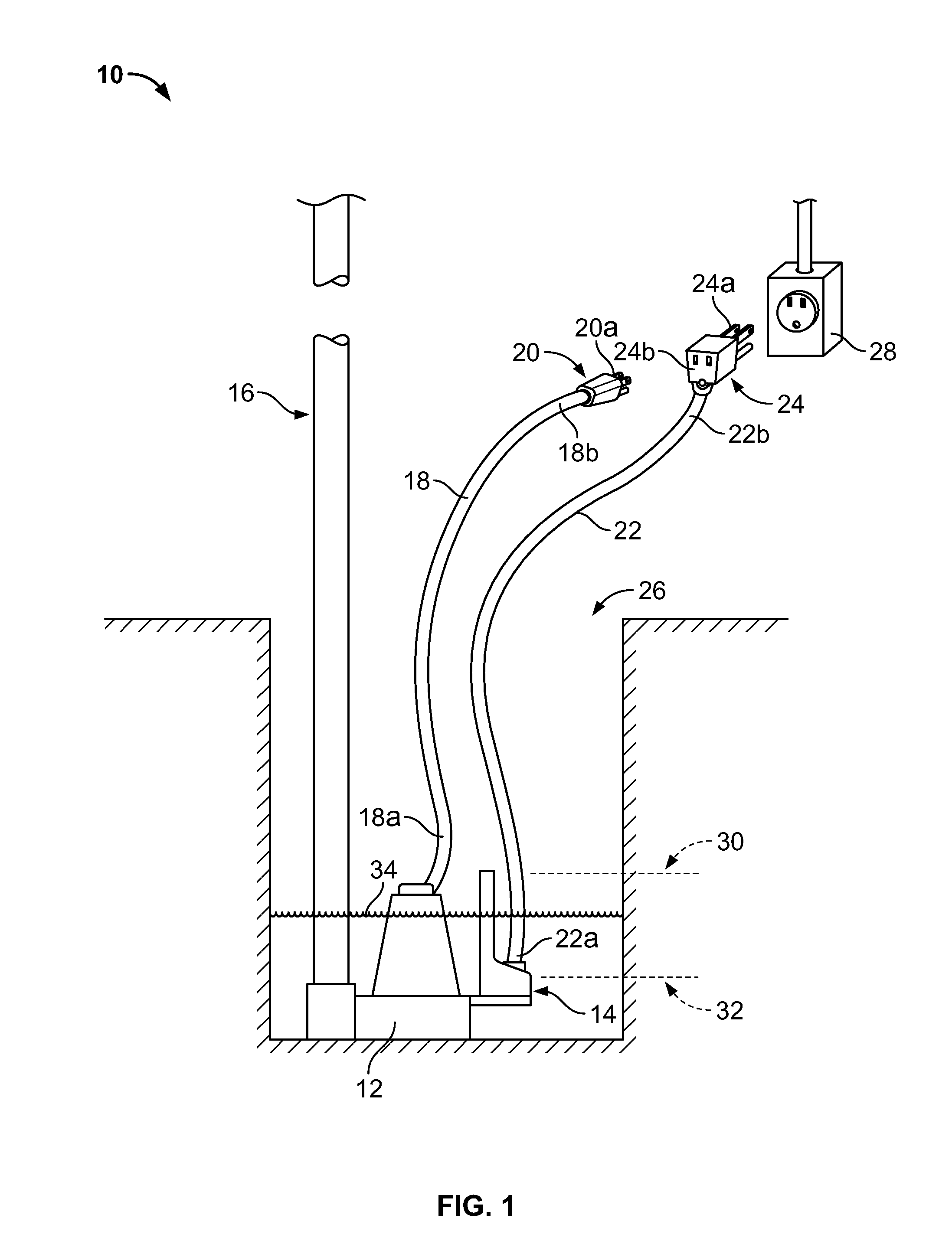
[0056]FIG. 1 depicts a sump pump system 10 disposed within a reservoir 26. The sump pump system 10 includes a pump 12, a sensor or sensor unit 14, and a discharge pipe 16. In general, the sensor unit 14 monitors the level of a liquid 34 within the reservoir 26 and serves as a switch for activating and deactivating the pump 12 based on that level. When the level of the liquid 34 reaches a predetermined upper limit, which is identified by reference numeral 30 in FIG. 1, the sensor unit 14 activates the pump 12. Upon activation, the pump 12 begins moving the liquid 34 up and out of the reservoir 26 via the discharge pipe 16. This begins to lower the level of the liquid 34 in the reservoir 26. Once the level of the liquid 34 reaches a predetermined lower limit, which is identified by reference numeral 32 in FIG. 1, the sensor unit 14 deactivates the pump 12. The details of the sump pump system 10 will now be discussed in more detail with continued reference to the figures.

[0057]FIG. 1 d...


PUM


Abstract

In one form a capacitive sensor is disclosed for immersion into a fluid, the capacitive sensor having a housing and first and second electrodes with the first electrode being disposed at least partially within the housing and electrically connected to a circuit, the second electrode being electrically connected to the circuit via an electrical connection and physically separated from the housing containing at least a portion of the first electrode so that at least a portion of the electrical connection or second electrode is located above or outside of the fluid to reduce the risk that minerals will form between the electrodes. In another form the electrodes are separated into their own cavities of the sensor housing via a bridging member which separates the electrodes to help reduce the risk of mineral buildup occurring between the electrodes. In other forms, capacitors, capacitive sensors, pump controls and systems utilizing these features are disclosed along with methods and apparatus relating to same. In yet other forms additional sensors such as current sensors, thermal sensors, speed sensors, torque sensors and Hall Effect sensors are disclosed for use alone or in combination with said capacitive sensor for detecting fluid level and / or controlling pumps. In still other forms, apparatus and methods relating to self cleaning pumps are disclosed.

Description

CROSS-REFERENCE TO RELATED APPLICATION[0001]This application is a continuation-in-part of prior U.S. application Ser. No. 12 / 617,377, filed Nov. 12, 2009, which is hereby incorporated herein by reference in its entirety.FIELD OF THE INVENTION[0002]The present invention relates to sensors and methods and apparatus relating to same. More particularly, the present inventions relates to capacitors, capacitive sensors, pump controls, pump systems and methods relating to fluid control and / or fluid level monitoring and / or control.BACKGROUND OF THE INVENTION[0003]Sensors are needed for a variety of applications. For example, pump applications, such as sump, dewatering, sewage, utility, effluent and grinder pumps, can use sensors to determine when the pump should be turned on and / or turned off. Conventional sump pumps generally include a pump having a mechanical switch connected to a float mechanism for controlling a liquid level in a reservoir. The float mechanism is disposed within the res...

Claims


Application Information

Patent Timeline
Patent Type & Authority Applications(United States)
IPC IPC(8): F04B49/06F04B53/00G01F23/26
CPCF04B23/021F04B49/065G01F23/268G01F23/266G01F23/265F04D13/086F04D15/0218
Inventor MAYLEBEN, PHILIPCOOPER, BUFORD A.STETTER, THOMAS
Owner MAYLEBEN PHILIP
Why Eureka
Try Eureka