LED light fixture

a technology of led light fixtures and led light fixtures, which is applied in the direction of lighting and heating apparatus, lighting support devices, and with built-in power, can solve the problems of heavy weight of conventional light fixtures, replacement components, and difficult manufacturing, and achieve the effect of less energy

Inactive Publication Date: 2007-10-25
INTEGRATED ILLUMINATION SYST
View PDF5 Cites 248 Cited by
  • Summary
  • Abstract
  • Description
  • Claims
  • Application Information

AI Technical Summary

Benefits of technology

[0014]Another object of the present invention is to package all or any of the electronic system components, wiring, optical components, reflectors, LED drivers, printed circuit board assemblies, batteries, battery back up circuitry, alarm circuitry, power supplies, wireless transmitter, diffusers, motion detectors, and cameras in a lightweight panel.
[0015]Still another object of the present invention is to operate in a variety of environments, including ones that are not suitable for conventional fixtures or panels due to their weight, installation problems, low thermal conduction, and low shock and corrosion resistance.
[0016]Yet another object of the present invention is to provide an LED fixture / panel that is low cost, waterproof, shock proof, fire resistant, acoustical, impact resistant, easy to assemble, and provides EMI shielding.
[0017]Still another object of the present is to provide a decorative panel / fixture that does not require extreme thermal conductivity and rigid structural integrity. The core of the panel may be less dense, have less core or heat conductive foam, and the outside upper skin may be a clear window or other material. This configuration may allow indirect and direct light distribution and low power LEDs.
[0020]According to another aspect of the present invention, a light panel / fixture using LEDs includes a lower metal skin layer possessing heat transfer properties. A printed circuit board is affixed to the lower skin, and the LEDs are bonded and soldered to the circuit board. When a DC voltage is applied to the LED or LEDs, they emit light through a window, which may be a hemispheric dome or other configurations based on the light emission angle desired. The light panel / fixture also includes a core possessing heat transfer properties that is in thermal contact with the LED or LEDs. The core is affixed to the lower skin layer and an upper skin layer containing a window over the LED. The LEDs conduct the heat from the lower skin through the core to the upper skin. This increases the thermally conductive surface area.
[0021]According to another aspect of the present invention, additional skin layers and cores may be between the upper and lower skin layers. This configuration allows more heat to be conducted to the upper skin and the lower skin through the core. This also allows for more high power LED applications. This configuration also allows light distribution to be vertically upward and vertically downward. In addition, more internal area is allowed for additional electronic and mechanical components.

Problems solved by technology

Conventional light fixtures are heavy in weight, difficult to manufacture, and have many replacement components as ballasts, which are potential failures in addition to the fluorescent bulb.
Instead, they gradually degrade in performance over time.
Also, LEDs produce directional light unlike conventional light sources that emit light in all directions, which causes a loss of intensity.
Despite the advantages of LEDs, current designs have several problems.
In present LED products and designs, the panels or fixtures are heavy in weight, expensive, and difficult to manufacture and install, and are not rugged or impact resistant.
Furthermore, the heat sinking is inadequate, most LED products are not waterproof, impact resistant, or antimagnetic.
Moreover, they cannot be trimmed or cut to size, and the products experience reduced life spans due to LEDs exceeding manufacturers' specified required thermal temperature limits.

Method used


Image

  • LED light fixture
  • LED light fixture
  • LED light fixture

Examples


Embodiment Construction

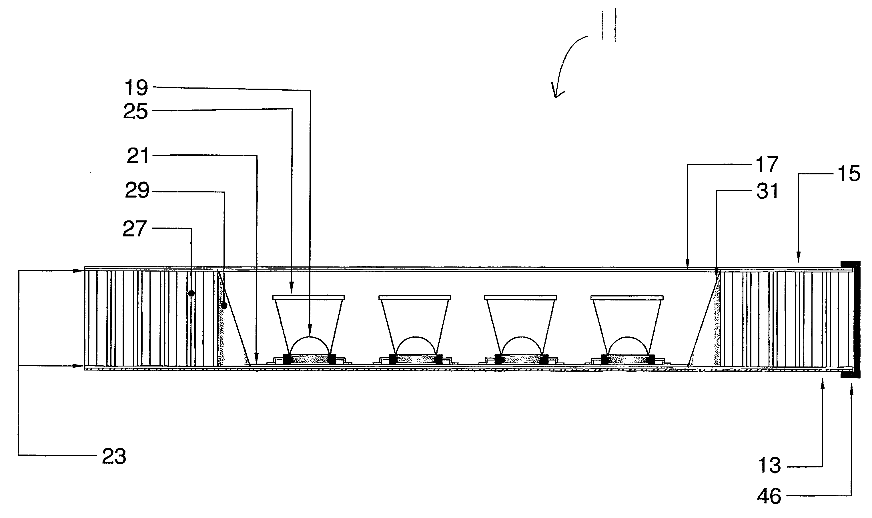
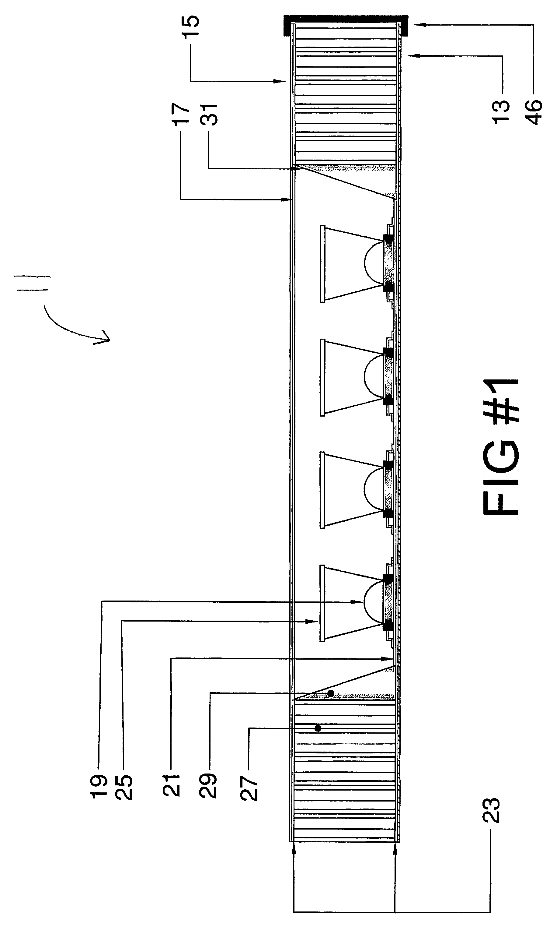
[0055]The present invention is directed to LED lighting structures that contain all the necessary functional components in a lightweight, sturdy panel or fixture. FIGS. 1, 2, and 3 show three embodiments of the present invention in a simplified schematic form. In FIGS. 1, 2, and 3, an LED light fixture / panel is encapsulated by a lower skin layer 13 and an upper skin layer 15. The lower skin layer 13 and upper skin layer 15 may be made in formed or flat configurations. A single or plurality of LEDs 19 is connected to a printed circuit 21 and is attached to the lower skin layer 13 by an adhesive, epoxy or thermal film 23. Also attached by adhesive, epoxy or thermal film 23 to the lower skin layer 13 is the core 27. Attached to the core by adhesive, epoxy or thermal film 23 is an upper skin layer 15.

[0056]The LEDs 19 have and optical component 25 and reflector 31. The upper skin 15 and the lower skin 13 may be flat or formed. The lower skin layer 13 can be of any thickness. Preferably,...


PUM


Abstract

A light fixture using LEDs includes a lower skin layer possessing heat transfer properties. A circuit board is affixed to the lower skin layer, and a single LED, or a plurality of LEDs, is electrically connected to the circuit board. The single LED, or plurality of LEDs, when electrically activated, emits light through substantially around a vertical axis. The light fixture also includes a core possessing heat transfer properties that is in thermal contact with the LED and has an interior cavity for the LED. The core is affixed to the lower skin layer, and an upper skin layer, containing a window or windows over the LED or LEDs, is affixed to the core. The LEDs may be white, infrared, ultraviolet, and / or colored and may be mounted on a printed circuit board or individually.

Description

CROSS REFERENCED TO RELATED APPLICATION[0001]This application claims the benefit of U.S. Provisional Application Ser. No. 60 / 794,819, filed on Apr. 24, 2006, hereby incorporated by reference in its entirety.FIELD OF THE INVENTION[0002]The present invention relates to a diversified LED fixture / panel, which can be of any size, geometric shape, flat, formed or combination thereof. The fixtures / panels may stand alone, be stacked, or be joined. The fixture / panel can be a structural or decorative panel. More particularly, it relates to an LED lighting system, which contains all necessary standardized components in a simplified lightweight fixture / panel. AC or DC voltage may be connected to the fixture panel which comprises of internal connectors, contacts, round conductive pins or wire connections, and any required on board circuits.BACKGROUND OF THE INVENTION[0003]As shown in FIG. 1A, light emitting diodes (LEDs) 19 work by connecting a power source to terminal pins 3 and sending the cur...

Claims


Application Information

Patent Timeline
Patent Type & Authority Applications(United States)
IPC IPC(8): F21V29/00
CPCF21S2/00F21V29/89F21S8/033F21S8/037F21S8/04F21S9/02F21S9/022F21S9/03F21V7/0016F21V15/01F21V21/005F21V23/04F21V23/0435F21V23/0442F21V33/0052F21V33/006F21W2121/00F21Y2101/02F21Y2105/001H05B33/0803H05B33/0842E04B9/006F21V29/74F21S8/02F21Y2105/10F21Y2115/10H05B45/00
Inventor ZAMPINI, THOMAS L.ZAMPINI, MARK A.
Owner INTEGRATED ILLUMINATION SYST
Why Eureka
Try Eureka