Integrated glass ceramic systems

a technology of glass and ceramics, applied in the field of integrated glass and ceramic systems, can solve the problems of limited system integration of various technologies, inability to significantly modify bulk mechanical, thermal and optical properties, and increase brittleness, so as to enhance internal optical communication, enhance dielectric properties, and increase strength

Active Publication Date: 2005-10-04
THE AEROSPACE CORPORATION
View PDF12 Cites 109 Cited by
  • Summary
  • Abstract
  • Description
  • Claims
  • Application Information

AI Technical Summary

Benefits of technology

[0013]Yet another object of the invention is to provide an integrated glass ceramic system having glass ceramic composite components with tempered and untempered glass portions for providing enhanced structural strength.
[0024]The spacecraft thermal control for a glass ceramic satellite is very different from a silicon or metallic satellite. Photostructurable glass ceramic materials can have a low thermal conductivity of 1.35 W / m-K for the glass phase which is less than stainless steel or aluminum used in conventional spacecraft. Due to the optical and near infrared transparency of the photostructurable glass ceramic materials, less than ten percent of received solar energy will be absorbed in the material while almost all of the infrared energy from the earth will be absorbed. This thermal absorption smoothes the temperature ranges for a satellite in Earth orbit where a significant fraction of the orbit is in eclipse. The high thermal insulating aspects of photostructurable glass ceramic materials can be thermally limiting for high power components, such as microprocessors and communication circuits. Fabrication of three-dimensional micro heat pipes, which are metalized and help to direct the heat away from these sources, can mitigate this thermal limitation of the photostructurable glass ceramic materials. These and other advantages will become more apparent from the following detailed description of the preferred embodiment.

Problems solved by technology

While there is a vast array of technologies available, system integration of various technology is limited due to operational compatibility and fabrication feasibility.
Silicon is an excellent choice as the main material for a spacecraft, but bulk mechanical, thermal, and optical properties cannot be significantly modified.
Ceramic materials are tougher than glass but also tend to be more brittle than the glass, and hence not generally suitable as a support structure in high tensile stress application.
Glass is weaker than ceramic, and susceptible to breakage during wide temperature operating range variations, but glass has superior optical transmission characteristics and can be brittle.
Ceramics can withstand higher temperatures than the glass, but have poor optical transmission characteristics.
Glass and ceramic materials differ in material properties, such optical transmission, electrical conductivity, thermal conductivity, and chemical resistance, offering operational incompatibility, and unsuitability for common use in a given application.
One problem associated with conventional metallic support structure is the mix of various supporting components and their various differences in thermal expansion coefficients, thermal conductivity, and optical properties that need to considered over the operational temperature ranges.
In addition, silicon and metallic support structures block visible optical transmission, limiting optical communications paths about the silicon or metallic support structures.
Further, silicon and metallic support structures have different material strengths rendering portions providing uneven structural strength about the support structure.
Further still, silicon and metallic support structures have limited molding and precise patterning manufacturing methods.

Method used


Image

  • Integrated glass ceramic systems
  • Integrated glass ceramic systems
  • Integrated glass ceramic systems

Examples


Embodiment Construction

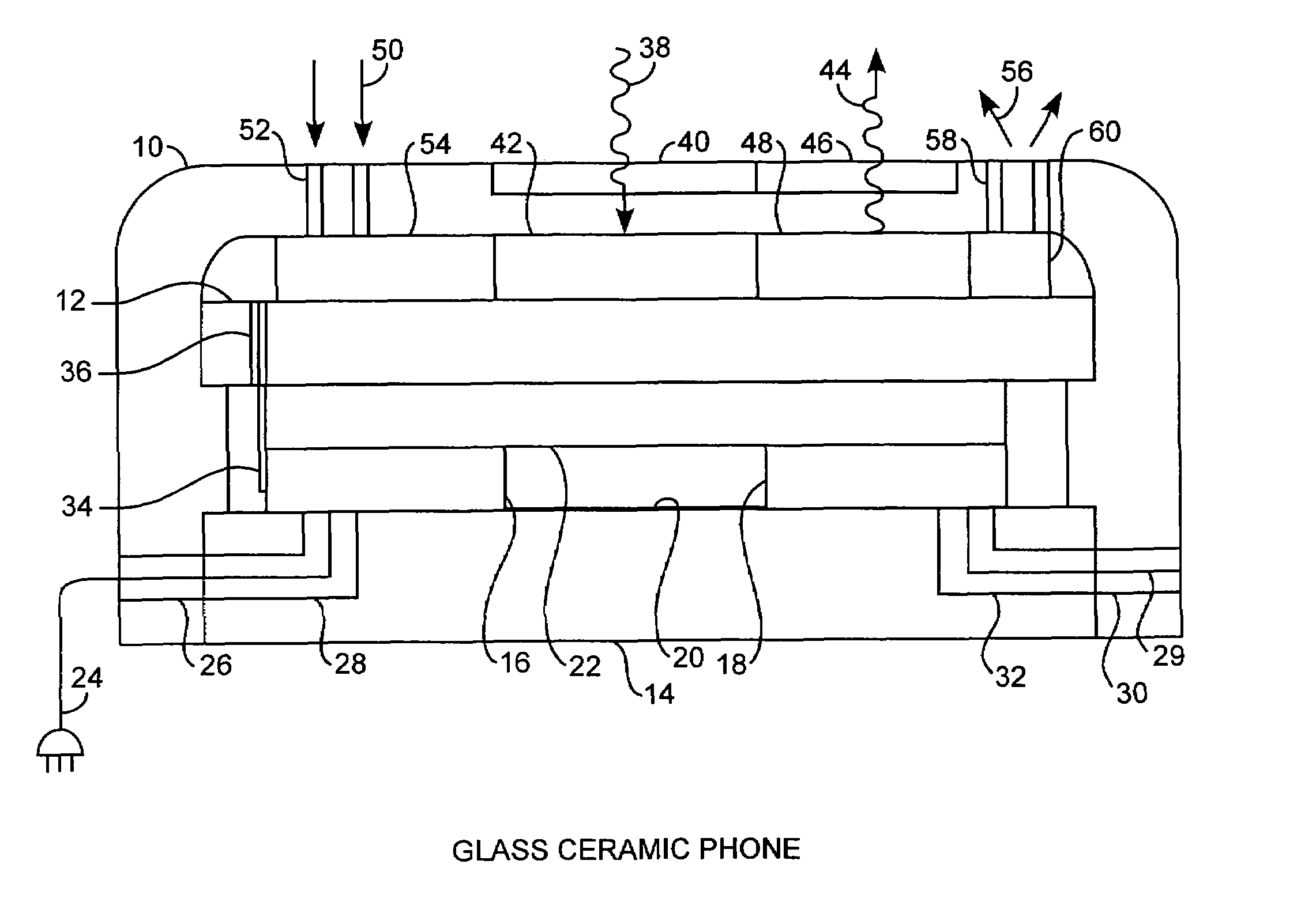
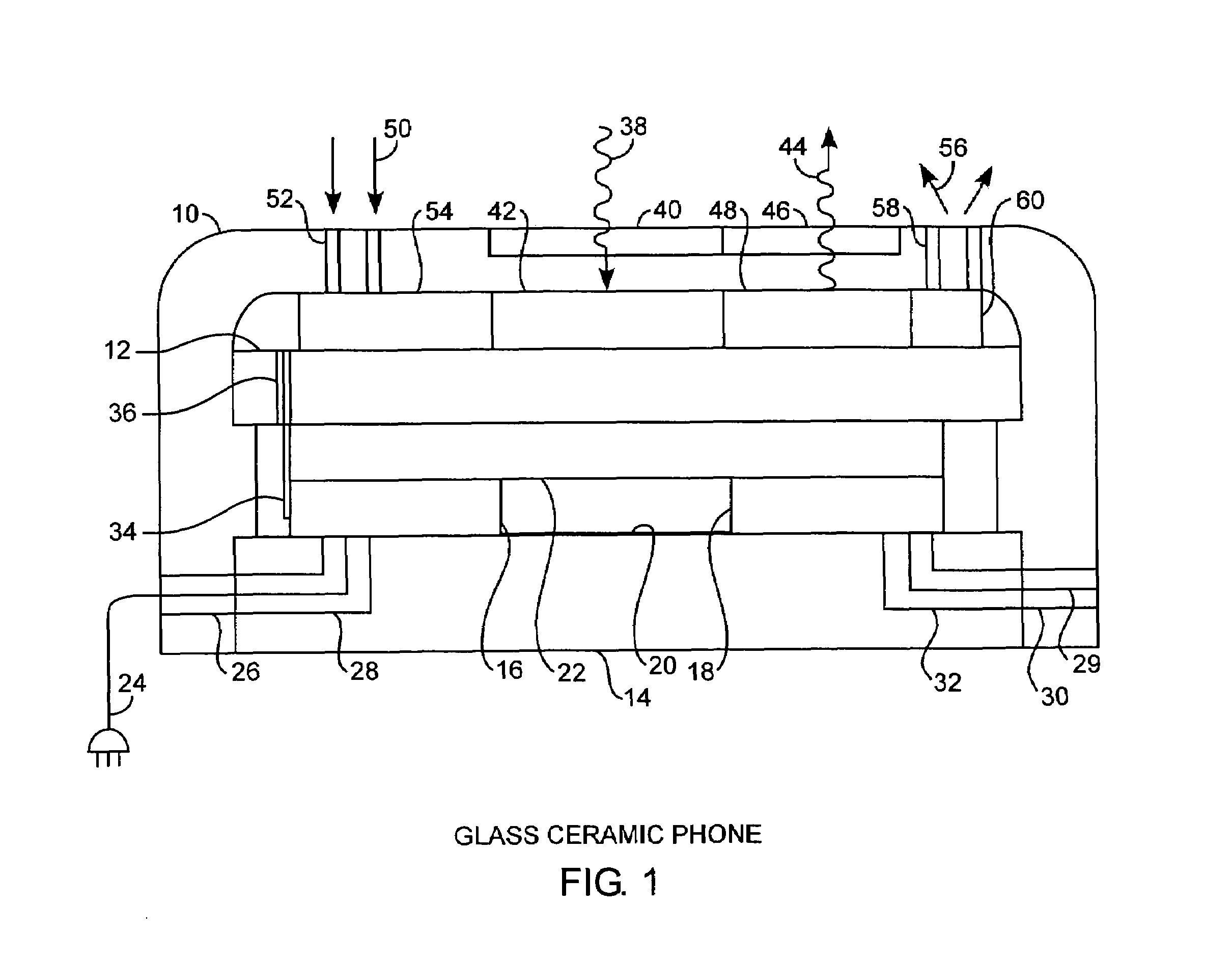
[0027]An embodiment of the invention is described with reference to the figures using reference designations as shown in the figures, Referring to FIG. 1, a glass ceramic phone, such as a cellular phone, can be adapted to include a variety of glass ceramic components in an all glass ceramic system. As used herein, a glass ceramic material is a material comprising glass or ceramic components, or both. A molded glass ceramic cover 10, a laser milled glass ceramic strut 12, and a laser milled glass ceramic base 14 form the structural components of the phone and collectively provide internal cavities for supporting encapsulated internal components. Internal to these structural components is a power converter 16 and a communications processor 18 connected together by horizontal interconnects 20. A thin film battery 22 is charged through an external power adapter 24 adapted for interface connection through a power cover feedthrough and a power base feedthrough 28 for connecting the power ...


PUM

PropertyMeasurementUnit
wavelengthsaaaaaaaaaa
near infrared transparencyaaaaaaaaaa
temperatureaaaaaaaaaa

Abstract

Integrated glass ceramic spacecraft include a plurality of glass ceramic components including molded, tempered, annealed, and patterned glass ceramic components coupled together for forming a support structure or frame or housing through which is communicated optical signals through an optical communications grid and electrical signals through an electrical communications grid, with the optical communications grid and electrical communication grid forming a composite electrooptical communications grid for spacecraft wide intercommunications. The support structure multifunctions as a frame, a housing, a support, a thermal control system, and as part of an electrooptical communications grid while encapsulating a plurality of optical, electronic, electrical, and MEMS devices between which is communicated the electrical and optical signals over the electrooptical communication grid.

Description

STATEMENT OF GOVERNMENT INTEREST[0001]The invention was made with Government support under contract No. F04701-00-C-0009 by the Department of the Air Force. The Government has certain rights in the invention,REFERENCE TO RELATED APPLICATION[0002]The present application is related to applicant's copending application entitled Glass Ceramic Spacecraft Ser. No. 10 / 742,058, filed Dec. 19, 2003, by the same inventors.FIELD OF THE INVENTION[0003]The invention relates to the fields of industrial art for making glass and ceramic components, tool and die arts for making molded glass and ceramic components, photostructurable arts for laser milling glass and ceramic components, semiconductor arts for fabricating semiconductors and hybrids, and for depositing conductor traces in an electrical communications grid, microelectromechanical arts for making active and passive MEMS devices, wafer flip and bond art for encapsulating electrical devices, MEMS devices, and optical devices, electrical arts...

Claims


Application Information

Patent Timeline
Patent Type & Authority Patents(United States)
IPC IPC(8): C03C10/00C03C15/00G02B6/42B64G1/10B64G1/26B64G1/36B64G1/40B64G1/42B64G1/44B64G1/66
CPCB64G1/10C03C10/00C03C15/00B64G1/26B64G1/361B64G1/402B64G1/425B64G1/443B64G1/66G02B6/4246
Inventor HELVAJIAN, HENRYJANSON, SIEGFRIED W.
Owner THE AEROSPACE CORPORATION
Why Eureka
Try Eureka