[0007] These and other objects are met by the industrial hopper and support of the present invention. That is to say, the present invention provides a significant improvement over the prior art by providing a bin which is complementally configured with the support so that the bin is carried by the legs of the support, rather than on a base extending between the supports. In this manner, not only is an aggressive slope for the sides of the bin permitted, but the weight of the bin and its contents are carried by essentially vertical and upright walls of the bin and the legs of the support. In addition, the support is efficiently configured to provide a stable
receiver for the forks of a forklift, with an economy of materials and wherein the support provides for a wide opening area at the bottom of the hopper.
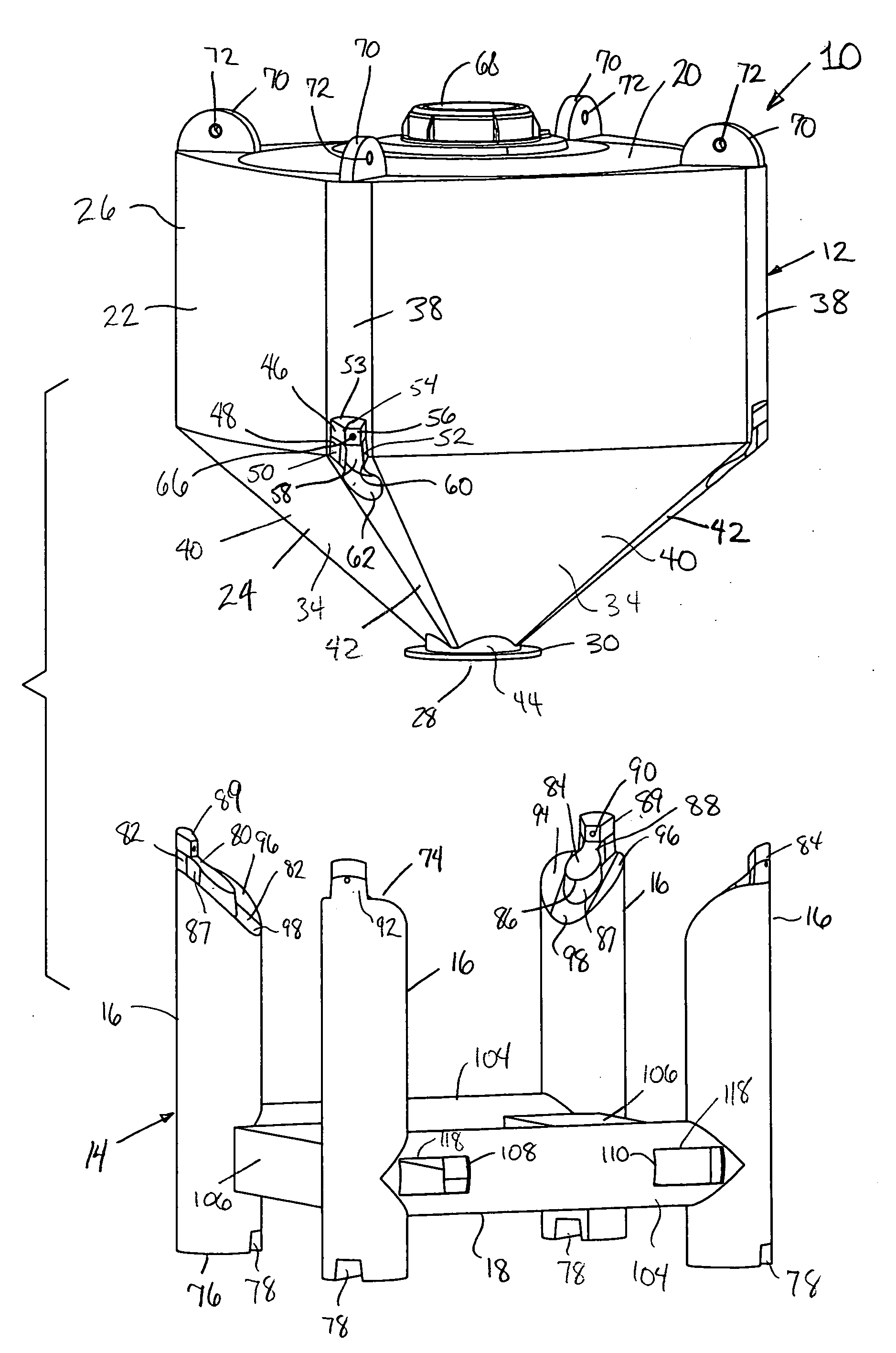
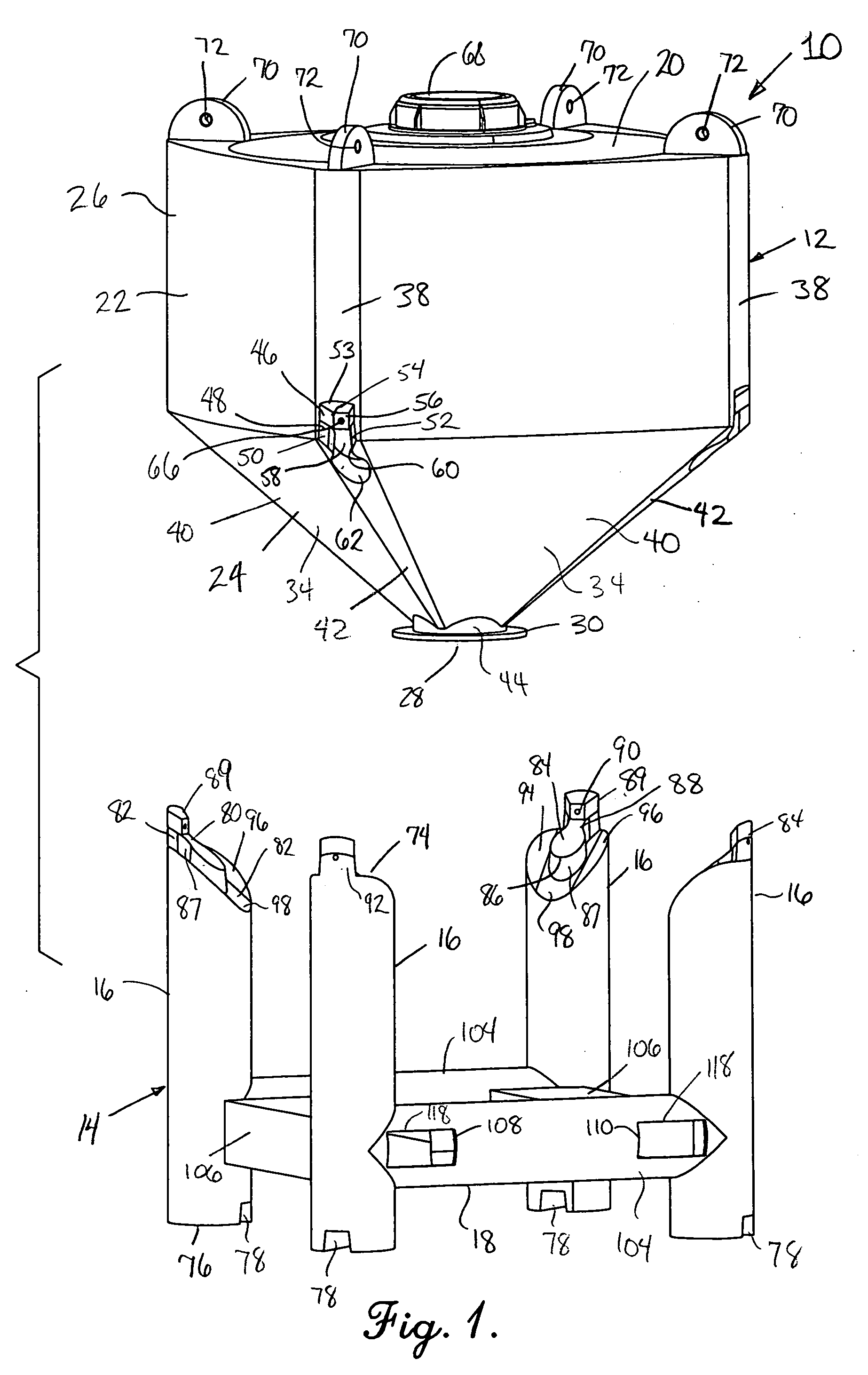
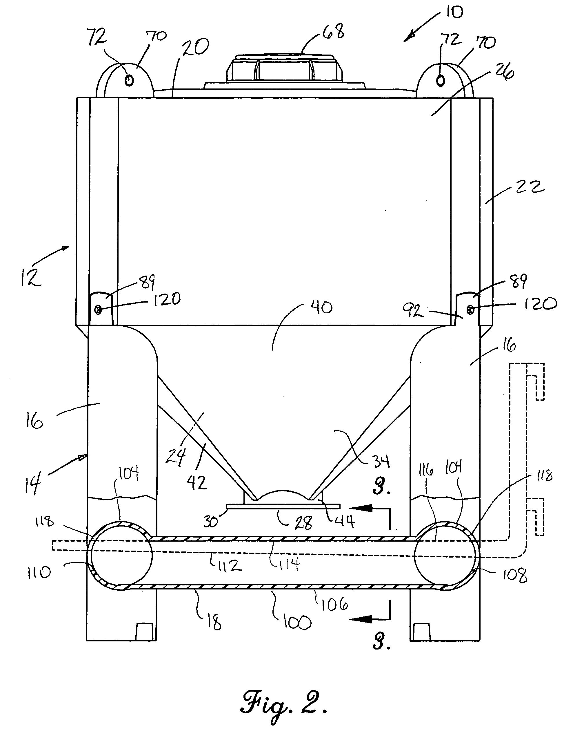
[0008] Broadly speaking, the present invention includes a hopper having an upright sidewall in an upper holding zone and a sloping sidewall in a dispensing zone leading to a wide opening for mounting a valve thereon, in combination with a complementally configured support having a plurality of spaced, substantially vertical legs for receiving the hopper thereon and tubular members for structurally connecting the legs. The hopper and the support are manufactured substantially by
rotational molding which enables the use of
synthetic resin materials which are both economical and resistant to
corrosion. The tubular members are arranged so that openings in primary members align with the cavities in at least two crossmembers to receive the forks of a forklift into the openings to provide a lifting surface on the top interior surfaces of the crossmembers. The legs are molded into and extend vertically from at least two of the tubular members so that the legs are held
proximate their lower ends.
[0009] As noted above, the hopper and its support are complementally configured, and preferably the hopper includes receivers molded into its sidewalls which receive and fit with the top ends of each of the legs. The receivers are most preferably spaced around the sidewall in
equidistant arrangement, and located where the upright sidewall transitions to the sloping sidewall. The receivers and top ends of the legs include interfitting recesses and lugs, such that once the lugs are received in the recesses, the legs are prevented from spreading at their top end. By this configuration, the weight of the hopper and its contents is transferred vertically, in compression, to the legs, and the structure of the receivers and the adjacent sidewalls provide structural support to
resist transverse spreading of the legs which could otherwise result in slipping of the hopper off of the support. Beneficially, however, the hopper may be readily separated from the support for dumping operations or the like by lifting the hopper by a crane off of the support. The particular configuration of the top surface of the legs and the recesses of the hopper is particularly advantageous because it facilitates the flow of the
solid materials within the hopper while at the same time does not require any additional fasteners to maintain the hopper on the support. However, the present invention also advantageously includes
coupling structure, for example an ear provided with a hole, whereby a bolt or other
fastener may be used so that the support is lifted along with the hopper, when desired. In preferred embodiments, the bin portion of the hopper sidewall may be substantially rectangular in plan, with the corners having an arcuate configuration which aligns with the outboard portion of the upright legs to present a substantially continuous vertical outer surface extending along the legs up and along the sidewall of the hopper at the corners to improve the structural strength of the combination.
[0010] The support permits the hopper to be supported directly on the legs, leaving a wide open area at the bottom of the support so that the opening of the hopper, and a valves coupled thereto, may be received in the opening. Thus, instead of a base in the form of planar or other surface extending substantially across the opening, the tubular members surround the open area. The tubular members link the legs together at their bottom end, with preferably four legs being provided. In this arrangement, two of the tubular members are primary members which are preferably centered on the upright legs, and two of the crossmembers extend between the primary members and are integrally formed therewith, and are spaced apart corresponding to the
standard distance of the forks of a forklift or
pallet-jack. Most preferably, the dimensions of the openings in the primary members are sized somewhat smaller than the cross-sectional internal dimensions of the crossmembers, but having the top margin of the openings aligned with the top interior surface, so that the openings in the primary members act as a visual guide to facilitate entry of the forks into the crossmembers. The top interior surface of each of the crossmembers is preferably flat to thereby permit the normally flat upper surface of the forks to rest thereagainst, thereby minimizing stress concentrations and providing a greater surface area to be supported by the fork.
[0011] As a result, a very enconomical, stable and easy-to-use hopper and support is provided. These and other advantages will be readily appreciated by those skilled in the art with reference to the description and drawings which follow.

