Panel stiffeners for blow-molded plastic containers

a technology of blow-molded plastic containers and stiffeners, which is applied in the field of plastic containers, can solve the problems of reducing the structural capacity of withstanding top loads, adding additional materials to manufacturing costs, and not preventing side wall deflection or improving overall rigidity

Inactive Publication Date: 2002-12-24
PARADIGM PACKAGING
View PDF18 Cites 86 Cited by
  • Summary
  • Abstract
  • Description
  • Claims
  • Application Information

AI Technical Summary

Benefits of technology

It is a further object of the present disclosure to provide load compensation and increased rigidity of plastic containers in response to externally applied loads.
It is yet another object of the present disclosure, to provide a plastic container that is efficiently and inexpensively manufactured.
The present disclosure is directed to a container structure having increased strength and rigidity due, at least in part, to at least one groove formed in the container. The container, due to the disclosed configuration, facilitates load compensation and stress relief in response to externally applied loads. The container provides increased structural strength to a container while being easily and efficiently manufactured. The container advantageously forms longitudinal stress paths to facilitate load compensation that increases axial stiffness and top-load strength. The structural improvements of the present disclosure are achieved without substantial increases in material costs, mold cycle time or tooling complexity.

Problems solved by technology

Inward flexing of the side walls accommodate volumetric shrinking but create undesirable corner deformations which reduce structural capability to withstand top loads.
Containers including ribs require additional material that adds to manufacturing cost.
Furthermore, they do not prevent side wall deflection or improve overall rigidity.
The annular grooves of these lightweight containers reduce the containers' resistance to top loading, making the containers susceptible to top load crushing.
Such increased wall thickness, however, requires increased material and mold cycle times, thereby increasing manufacturing cost.
Such designs include decorative shapes and embossed lettering, typically requiring increased material which adds to cost.
However, these designs may only provide marginal or incidental increases in structural stiffness.

Method used


Image

  • Panel stiffeners for blow-molded plastic containers
  • Panel stiffeners for blow-molded plastic containers
  • Panel stiffeners for blow-molded plastic containers

Examples


Embodiment Construction

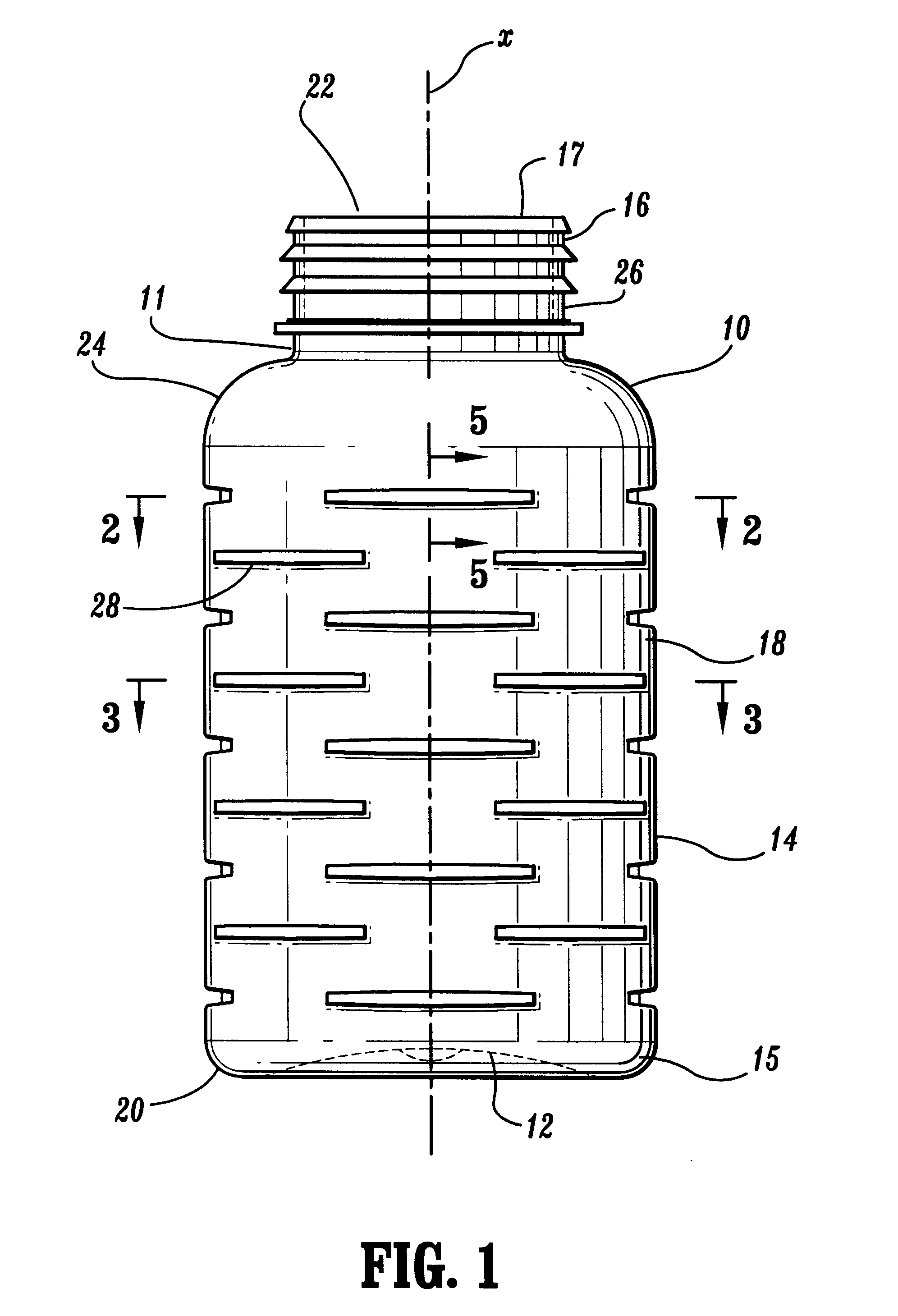
The exemplary embodiments of the apparatus and methods disclosed herein are discussed in terms of plastic containers. It is envisioned, however, that the disclosure is applicable to a wide variety of containers and vessels which require enhancement of axial or radial strength and rigidity. It is believed that the present disclosure finds application in various cylindrical objects such as piping, columns or cylinders, paper / plastic cups and packaging material, which require added strength and rigidity in axial and / or side wall deflection without the added requirements of additional panel wall thickness.

In the discussion which follows, the term "container"refers, but is not limited to, blow molded plastic bottles which employ snap-on, pushed-on, screw-on, etc., cap structures. It is important to note, however, that the present disclosure is readily applicable to containers, bottles, cups, dishes and cookware, e.g., TUPPERWARE.RTM., which would have the benefit of applying the present ...


PUM


Abstract

A container is provided which includes a top portion having an opening and a side wall extending from the top portion to an end portion of the side wall. A bottom portion is connected with the end portion of the side wall such that the top portion, the side wall and the bottom portion define an interior space of the container. At least one groove is formed in the side wall. The at least one groove includes a central arc portion and end arc portions. The central arc portion is substantially concave relative to a longitudinal axis of the container. The end arc portions are substantially convex relative to the longitudinal axis of the container. The end arc portions are formed adjacent ends of the central arc portion and communicate with an outer surface of the side wall. Desirably, the at least one groove includes a plurality of grooves. The plurality of grooves may be disposed within the rows in an interrupted configuration such that at least a portion of the outer surface is disposed between the plurality of grooves. The central arc portion and the end arc portion may be cooperatively formed to create a load stress path communicating with the outer surface of the side wall for a load applied to the container. In an alternative embodiment, the at least one groove defines a cross-sectional configuration having groove walls extending inward from the outer surface to a groove floor. The groove walls are oriented at a wall angle measured from the outer surface.

Description

1. Technical FieldThe present disclosure relates generally to the field of plastic containers, and more particularly, to panel stiffening features associated with the side walls of plastic containers.2. Background of the Related ArtContainers such as those described in the present disclosure are used for storing foodstuffs, medicine, liquids, and many other materials. Certain containers must withstand radial side wall forces and axial top loading forces. For example, certain containers must be rigid enough to resist side wall collapse due to internal vacuums that may develop from storing materials therein. Other containers are required to withstand radial forces during label application operations or axial forces during capping operations.Plastic containers, specifically blow molded plastic containers, are manufactured in various shapes to achieve structural advantages and aesthetic function. Specifically, it is known to provide container side walls with troughs, extensions and deco...

Claims


Application Information

Patent Timeline
Patent Type & Authority Patents(United States)
IPC IPC(8): B65D1/02
CPCB65D1/0223B65D2501/0036
Inventor ELLIS, DOUGLAS S.ZATS, ALEKSEYBARLICS, THOMAS G.NYMAN, HENRY H.
Owner PARADIGM PACKAGING
Why Eureka
Try Eureka