Four-degree-of-freedom parallel robot

Inactive Publication Date: 2003-02-11
PIERROT FRANCOIS +2
View PDF15 Cites 178 Cited by
  • Summary
  • Abstract
  • Description
  • Claims
  • Application Information

AI Technical Summary

Problems solved by technology

It is impossible to dispense with these actuators.
Therefore, there is inevitably a limit imposed on an attempt to cut down the cost.
This limit makes the six-degree-of-freedom parallel robot expensive.
However, in the robot of the related art II, since a torsional moment is applied to the torque rod, it is difficult to accomplish a movement at a high speed and a high acceleration as intrinsically require

Method used


Image

  • Four-degree-of-freedom parallel robot
  • Four-degree-of-freedom parallel robot
  • Four-degree-of-freedom parallel robot

Examples


embodiment i

of Embodiment I)

As a modification example I of this embodiment, it is possible to realize a four-degree-of-freedom parallel robot which is different from the embodiment I in combination of mounting angles of the actuators 2 and the parallel linkages 3 to the base 1 and the traveling plate 4.

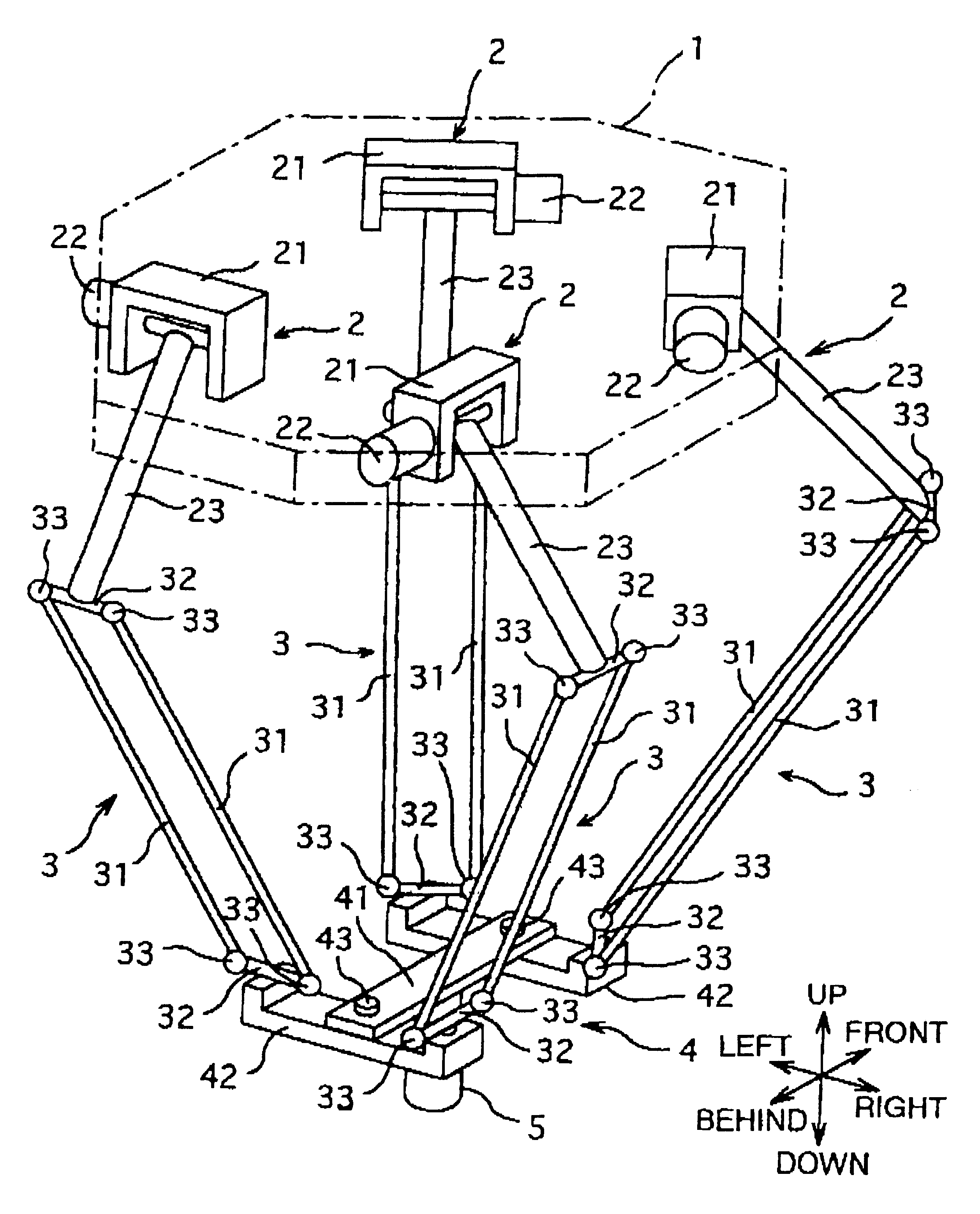
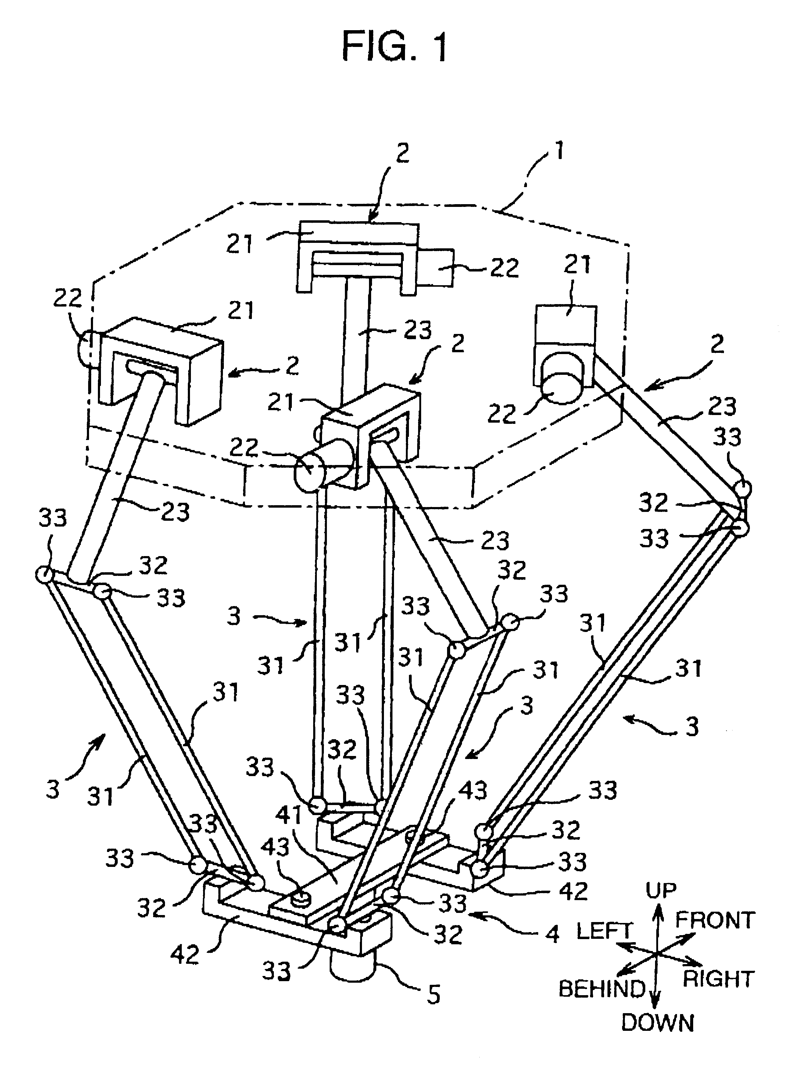
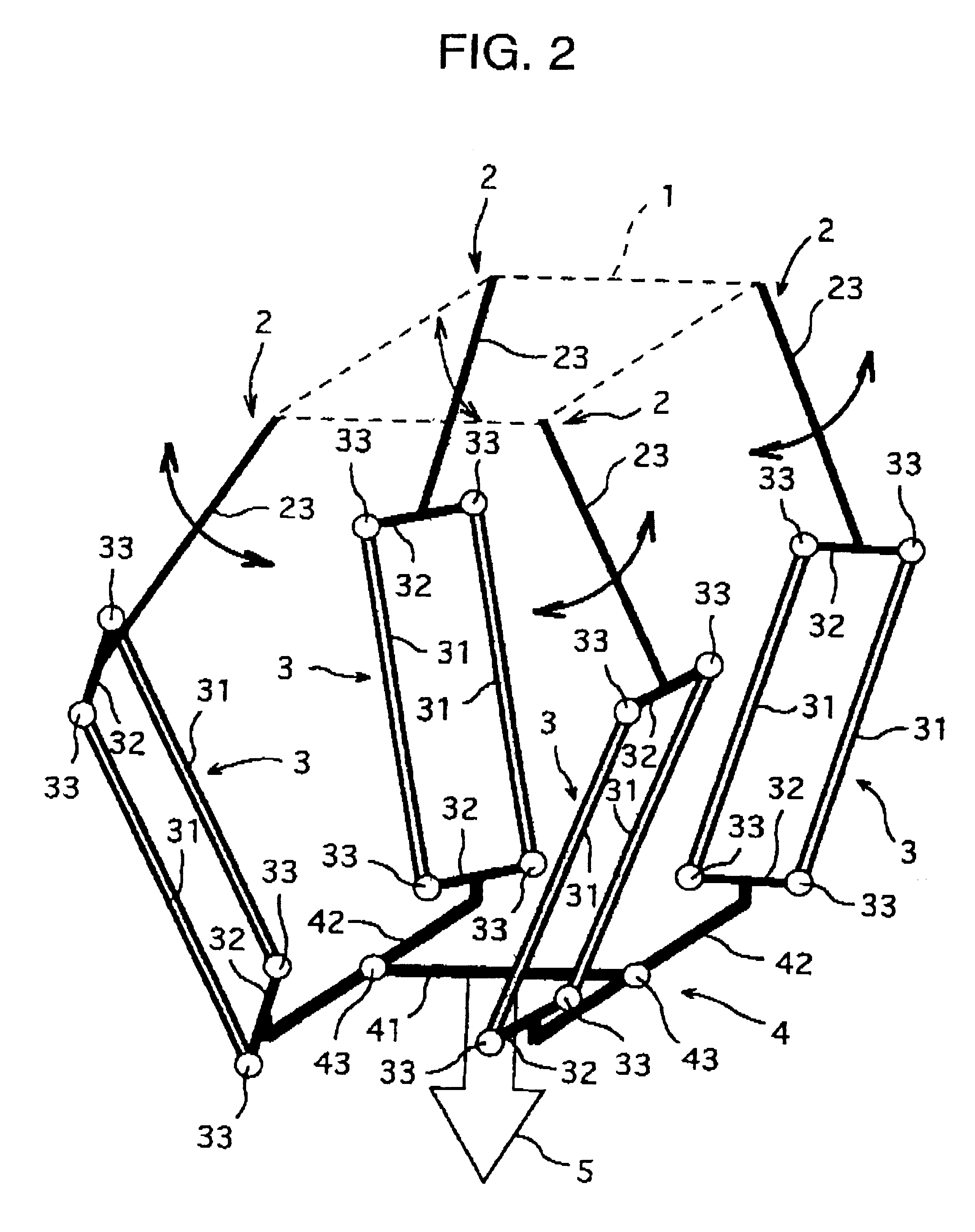
In this modification example, directions of the parallel linkages 3 are coupled to the four corners of the traveling plate 4 can be combined as will be described below. That is, assuming a predetermined direction as a reference direction around the vertical axis which is an axis of rotational motion, the following combinations are possible in one rotational direction. In this case, the mounting angles of the parallel linkages 3 are mounting angles of the end members 32 at lower ends of the four parallel linkages 3 with respect to the traveling plate 4. It is recommended to refer to these mounting angles in conjunction with FIG. 3.

That is, mounting angles of the parallel linkages 3 in this modific...

modification example ii of embodiment i

(Modification Example II of Embodiment I)

As a modification example II of this embodiment, as shown in FIG. 10, it is possible to realize a four-degree-of-freedom parallel robot which has four linear motors 2' as actuators in place of the four rotational motors 22 of the embodiment I. The linear motors 2' serving as actuators are secured to two bases (not shown). Rails of the linear motors 2' are secured at upper end portions to one of the bases, and at lower end portions to the other base.

Each of the linear motors 2' is composed of a vertically extending long rail which is alternately magnetized and a slider which moves along the rail and into which an electromagnetic coil is built. The end member 32 at the upper end of the parallel linkage 3 is fixed to each slider at a predetermined angle. The rails of the four linear motors 2' extend vertically and are disposed in parallel with one another.

Therefore, due to the operation of the linear motors 2', the end members 32 at the upper en...

modification example iii of embodiment i

(Modification Example III of Embodiment I)

As a modification example III of this embodiment, as shown in FIG. 11, it is possible to realize a four-degree-of-freedom parallel robot which has two linear motors 2' as actuators in place of the four rotational motors 22 of the embodiment I. Unlike the aforementioned modification example II, this modification example employs two linear motors 2' whose rails are disposed horizontally in parallel with one another. Although not shown, two bases are provided to secure the linear motors 2' serving actuators. Rails of the linear motors 2' are secured at both ends to the bases.

Each of the linear motors 2' is composed of a horizontally extending long rail which is alternately magnetized and a pair of sliders which move along the rail and into which electromagnetic coils are built. The end members 32 at upper ends of the parallel linkages 3 are fixed to the sliders at predetermined angles. The two rails of the linear motors 2' extend horizontally a...


PUM


Abstract

A four-degree-of-freedom parallel robot capable of displacing a traveling plate with four degrees of freedom at a high speed and a high acceleration and positioning the traveling plate with high rigidity and high precision. The four-degree-of-freedom parallel robot has four actuators fixed to a base, four parallel linkages each of which is coupled at its upper end to a tip end of an arm of each of the actuators through a kinematic element such as a universal joint, and a traveling plate whose four corners are coupled to lower ends of the parallel linkages through kinematic elements. By controlling the actuators, a main member of the traveling plate is displaced with four degrees of freedom, i.e., translated in all directions and rotated around a predetermined axis. Only axial forces are applied to rods constituting the parallel linkages. Thus, the traveling plate can be positioned at a high speed and with high rigidity as well as high precision.

Description

INCORPORATION BY REFERENCEThe disclosure of Japanese Patent Application No. HEI 11-264311 filed on Sep. 17, 1999 including the specification, drawings and abstract is incorporated herein by reference in its entirety.1. Field of the InventionThe present invention relates to a technical field of a parallel robot wherein a plurality of actuators are disposed in parallel. Although the present invention is suited for an industrial robot designed for transportation, processing or machining, it is also widely applicable to other devices such as a driving simulator for a motor vehicle.2. Description of the Related ArtThe industrial robot is classified into a serial robot such as an arm-type robot with a serial linkage mechanism wherein actuators are disposed in series and a parallel robot such as a flight simulator with a parallel linkage mechanism wherein actuators are disposed in parallel. In the parallel robot, unlike the case with the serial robot, there is no bending moment applied to ...

Claims


Application Information

Patent Timeline
IPC IPC(8): B25J17/02B23Q5/26B25J11/00B25J19/00F16H21/46
CPCB25J17/0266B25J9/0051A61B2019/2226Y10T74/20305Y10T74/20317A61B2034/304
Inventor PIERROT, FRANCOISCOMPANY, OLIVIERSHIBUKAWA, TETSUROMORITA, KOJI
Owner PIERROT FRANCOIS
Why Eureka
Try Eureka