Filter and forming system

a filter and forming system technology, applied in the field of filtering fluid, can solve the problems of not being able to produce media with the desired geometry and structure, media to fold or crease into pleats along the score lines, and achieve the effect of more structural stability, less laminar flow, and not adversely affecting the performance of the filter

Inactive Publication Date: 2005-09-20
FLEETGUARD INC
View PDF33 Cites 83 Cited by
  • Summary
  • Abstract
  • Description
  • Claims
  • Application Information

AI Technical Summary

Benefits of technology

[0006]Another possibility is to use corrugation for producing a filter. In this method, corrugated rollers are used to imprint a shape onto the media, instead of creasing and folding the media as is done with other pleating methods. The limitation of the noted corrugation method is that the pleats have a sinusoidal cross-section, rather than triangular or trapezoidal. As above noted, triangular or trapezoidal flutes or channels are desired, with cross-sectional geometries which are more structurally stable and provide for more laminar flow.
[0007]In one aspect of the invention, a star gear pleating method is used to produce the pleated media filter. Particularly designed interlocking gears pass the media between one or more sharp tips of a gear tooth on one gear and a particularly formed root of the opposing gear. The teeth can be modified to provide triangular or trapezoidal pleats. The gears fold and gather the media without crushing it and without adversely affecting the performance of the filter. As the media is released from the interlocking gears, it is directed forward and out of the gears by guide bars which prevent the media from tending to follow the gears and become damaged. The present method does not rely on media stiffness to fold and crease the media, and hence it can be used on more pliable media without damage to the pleat tips. The media is partially gathered and folded between the interlocking teeth of the gears, which partial gathering helps prevent unwanted jams or reverse pleating otherwise common with score-roll pleating. The present method and forming apparatus allows much shorter pleat heights and faster pleating without damaging the media or breaking media fibers. In contrast to corrugation, the present technique provides straight sided triangular or trapezoidal pleats.

Problems solved by technology

Conventional methods, including score-roll pleating and corrugation, cannot produce media with the noted desired geometry and structure.
The inherent stiffness of the media causes the media to fold or crease into pleats along the score lines.
For this reason, score-roll pleating is unsuitable for pliable media with insufficient stiffness.
Another limitation is that desired small pleat heights in certain applications, e.g. less than 10 mm, cannot be obtained by the score-roll pleating method.
Furthermore, creasing along the noted score lines can damage the media pleat tips for some types of filter media.
The limitation of the noted corrugation method is that the pleats have a sinusoidal cross-section, rather than triangular or trapezoidal.
As the media is released from the interlocking gears, it is directed forward and out of the gears by guide bars which prevent the media from tending to follow the gears and become damaged.

Method used


Image

  • Filter and forming system
  • Filter and forming system
  • Filter and forming system

Examples


Embodiment Construction

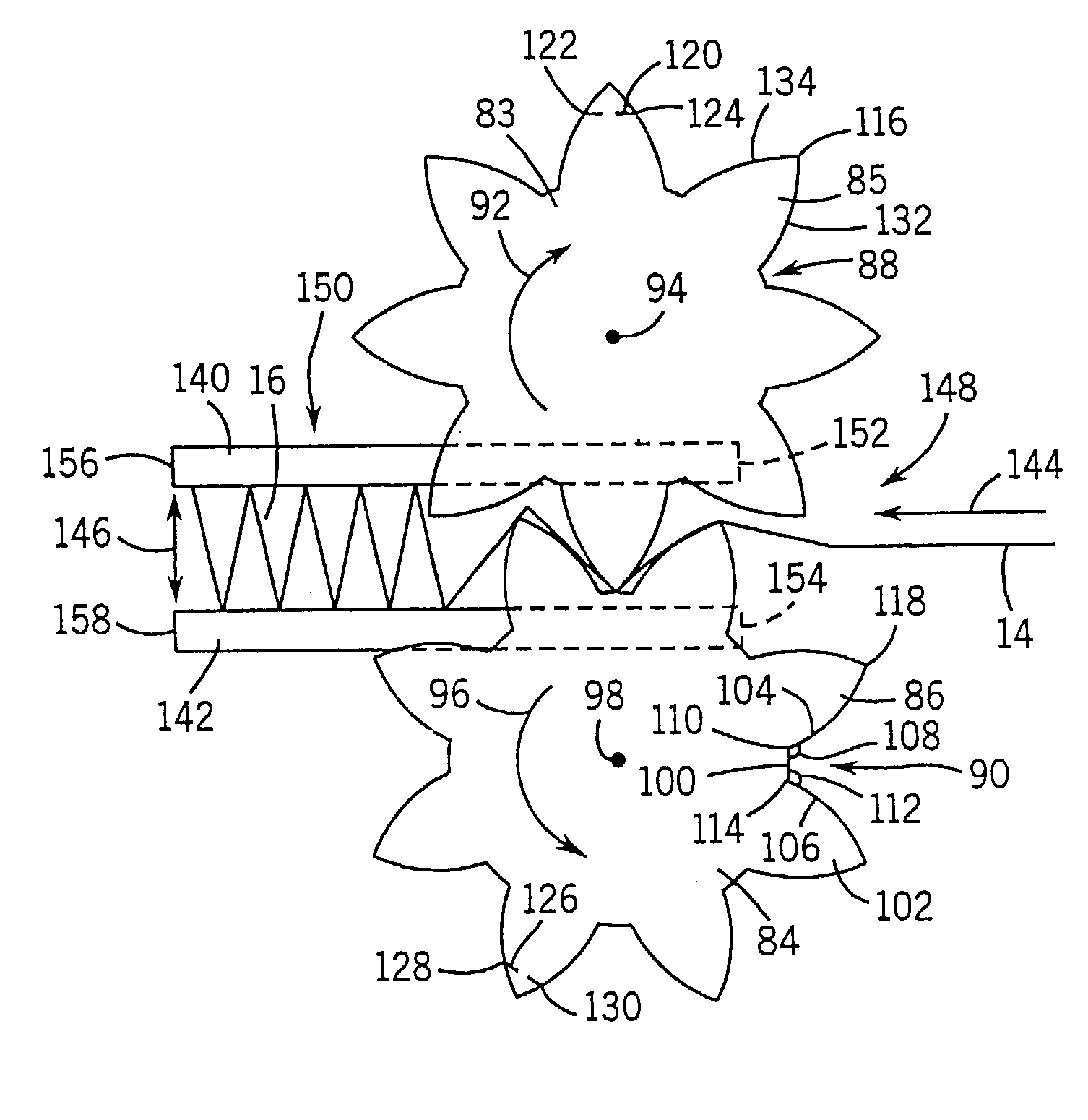
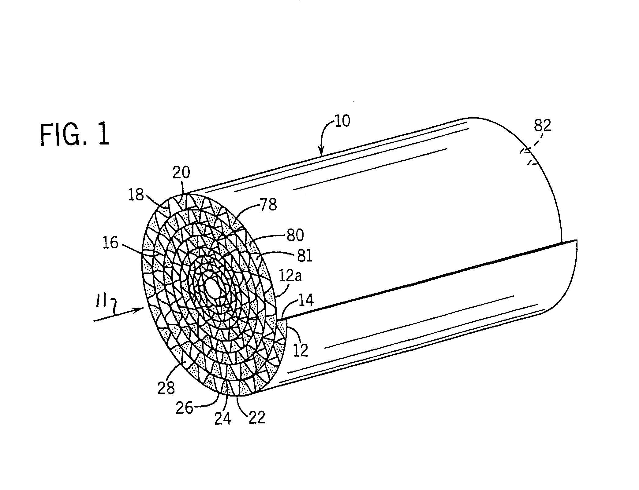
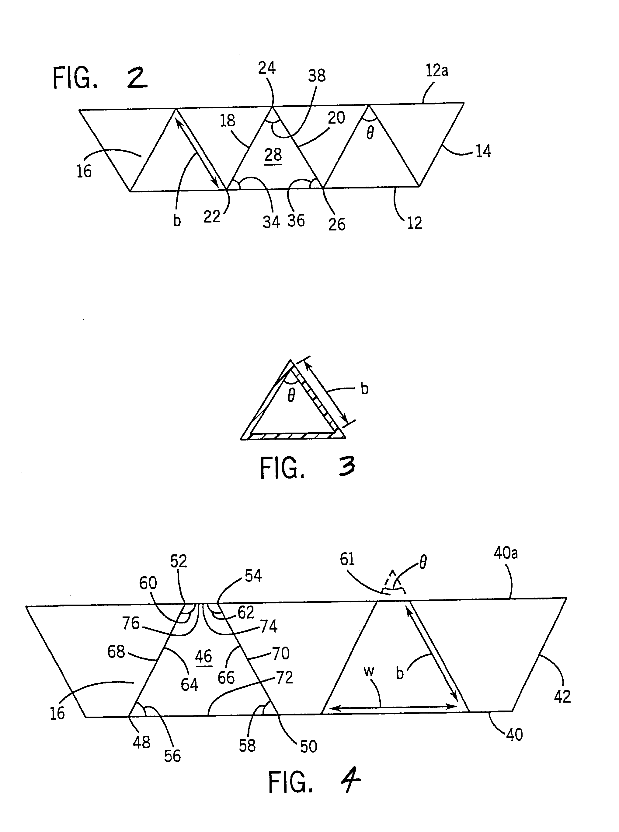
[0014]FIG. 1 shows a filter 10 for filtering fluid flowing axially thereinto as shown at arrow 11. The filter includes first and second filter media sheets 12 and 14. Sheet 14 has a plurality of pleats such as 16 defined by wall segments 18, 20, etc. extending in zig-zag manner between pleat tips 22, 24, 26, etc., FIGS. 1, 2, at axially extending bend lines. The pleat tips such as 22 and 26 on one side of sheet 14 are in contiguous relation with sheet 12 and preferably bonded thereto with an adhesive or other binder, and define axial flow channels such as 28. Sheets 12 and 14 are preferably, though not necessarily, wound or rolled into a spiral, FIG. 1. In a spiral-wound or other multilayer stack, the pleat tips such as 24 on the other side of sheet 14 engage sheet 12 of the next layer, for example as shown at 12a, FIG. 2.

[0015]The noted flow channels such as 28 have a lateral cross-sectional shape having two adjacent included angles each greater than 45° and less than 75°. In one e...


PUM

PropertyMeasurementUnit
included anglesaaaaaaaaaa
heightaaaaaaaaaa

Abstract

A filter includes first and second sheets of filter media, the second sheet being pleated and forming with the first sheet a plurality of axially extending flow channels having lateral cross-sectional shapes with two adjacent included angles each greater than 45° and less than 75°. Forming apparatus and methods are provided.

Description

CROSS-REFERENCE TO RELATED APPLICATIONS[0001]This application is a continuation-in-part of U.S. patent application Ser. No. 09 / 935,847, filed Aug. 23, 2001, now U.S. Pat. No. 6,582,490 which is a continuation-in-part of U.S. patent application No. 09 / 573,747, filed May 18, 2000, now U.S. Pat. No. 6,444,006, both incorporated herein by reference.BACKGROUND AND SUMMARY[0002]The invention relates to filters for filtering fluid, including air, exhaust, liquid, and other fluids, and to forming apparatus and methods for such filters.[0003]The filter is formed by alternating layers of flat and pleated filter media. In one embodiment, the layers are rolled into a cylindrical or other closed loop shape, such as oval, racetrack shaped, etc. The channels formed by the intersection of the rolled pleated and flat layers run in an axial direction to the cylindrical structure along its length. Lower restriction and greater structural strength is provided, including crush strength, which is desirab...

Claims


Application Information

Patent Timeline
Patent Type & Authority Patents(United States)
IPC IPC(8): B01D46/52B31F1/20B31F1/22B01D46/00B01D46/10B31D3/00
CPCB01D46/0001B01D46/10B01D46/525B31D3/002B01D2258/012B01D2275/10Y10T156/1016B01D2279/30Y10S55/05Y10S264/48Y10S55/30B01D2275/206
Inventor MILLER, ROBERT K.LIU, Z. GERALDHABERKAMP, WILLIAM C.VERDEGAN, BARRY M.SCHUKAR, MURRAY R.DEMIRDOGEN, A. CANER
Owner FLEETGUARD INC
Why Eureka
Try Eureka