
High flow spool valve

a spool valve and high flow technology, applied in the field of valves, can solve the problems of increasing the envelope size, reducing efficiency, and challenging the high flow coefficient “cv” of the valve, and achieve the effect of improving efficiency and improving flow through the valv

Active Publication Date: 2017-07-13
AUTOMATIC SWITCH
View PDF5 Cites 0 Cited by
  • Summary
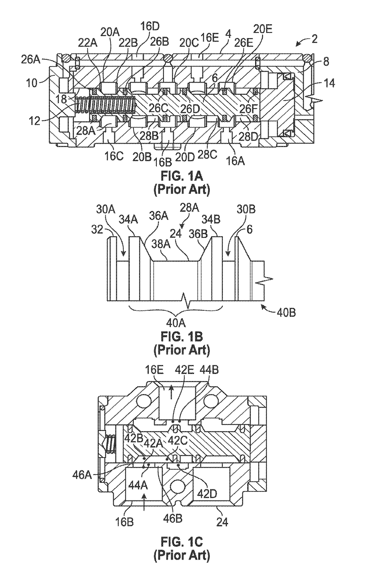
  • Abstract
  • Description
  • Claims
  • Application Information

AI Technical Summary

Benefits of technology

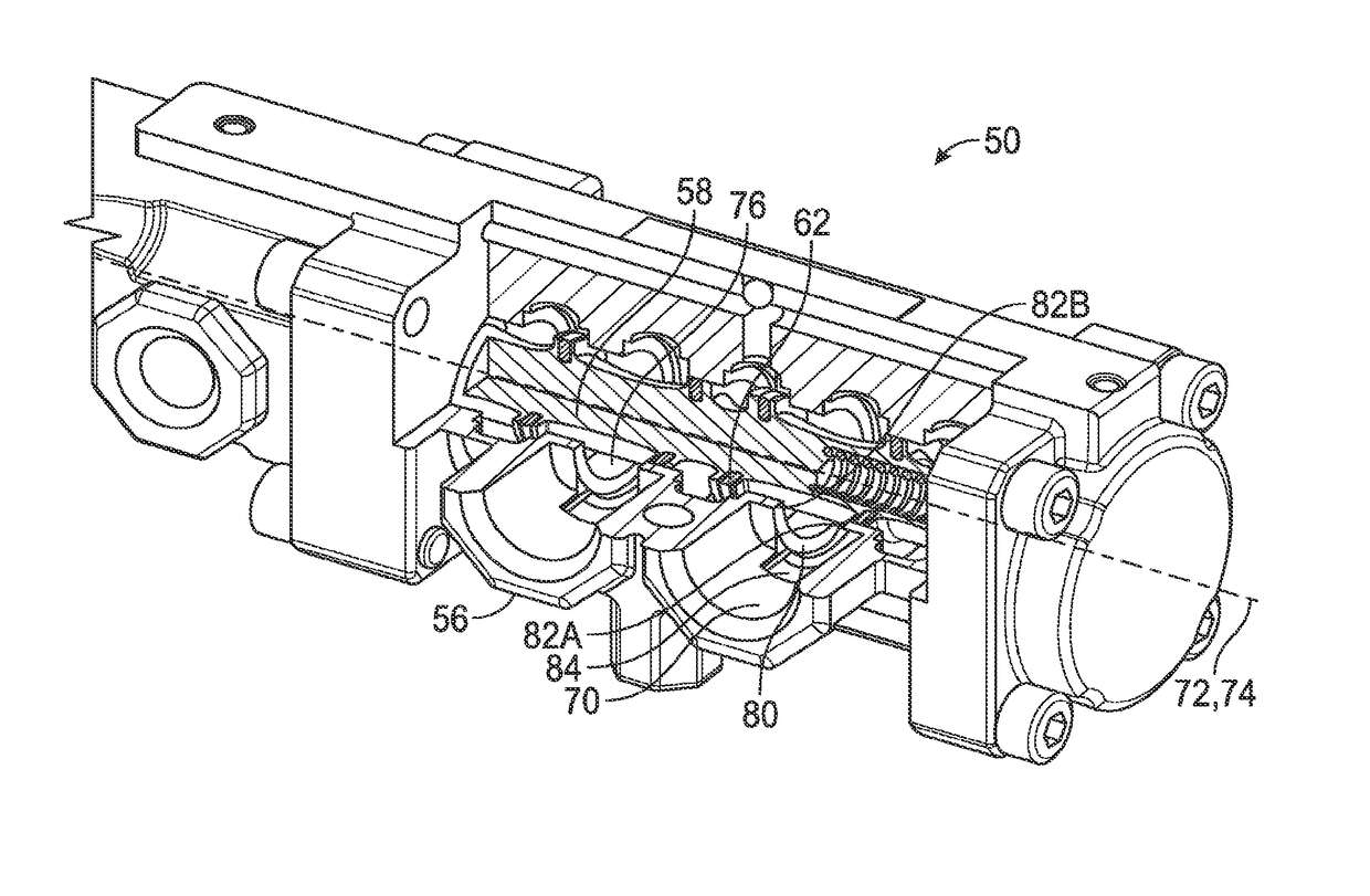
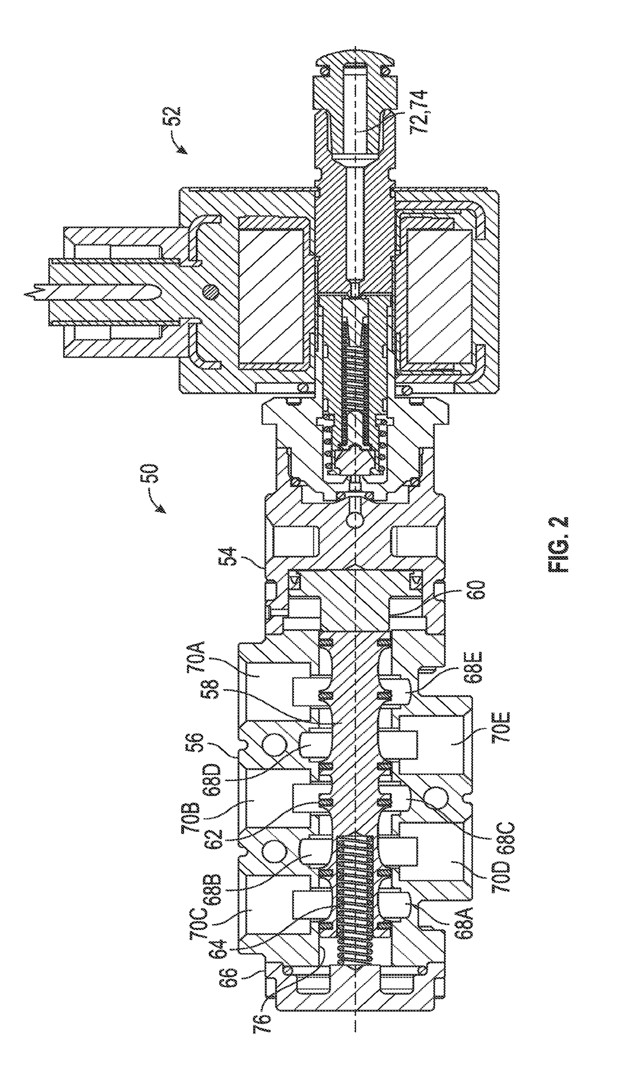
The present invention is a high flow coefficient spool valve that improves the flow of a conventional spool valve. The valve has spherically contoured internal grooves and concave surfaces between seals that complement the spherical shape of the grooves. This design allows for more volume and more laminar flow, resulting in an increased flow coefficient and flow capacity. The spool valve also has transverse port windows that contour into a bore of the valve body. An internal choke volume is strategically designed in a parallel flow location to promote laminar flow and lessen turbulence. The improved spool valve has a flow coefficient that is about a 26% increase compared to a commercially available spool valve.

Problems solved by technology

The challenge in valve design is efficient, controlled flow.
A high flow coefficient “Cv” is especially challenging for multiport spool valves that switch between multiple ports for directing flow, based on positions of the spool within a valve body.
The various flow passages in a spool valve inherently create flow restrictions and lessen efficient performance.
However, some applications are not conducive to an overall increase in the envelope size, so increasing the flow efficiency independently of increasing the body size has historically been challenging.

Method used


Image

  • High flow spool valve
  • High flow spool valve
  • High flow spool valve

Examples


Embodiment Construction

[0043]The Figures described above and the written description of specific structures and functions below are not presented to limit the scope of what Applicant has invented or the scope of the appended claims. Rather, the Figures and written description are provided to teach any person skilled in the art to make and use the inventions for which patent protection is sought. Those skilled in the art will appreciate that not all features of a commercial embodiment of the inventions are described or shown for the sake of clarity and understanding. Persons of skill in this art will also appreciate that the development of an actual commercial embodiment incorporating aspects of the present disclosure will require numerous implementation-specific decisions to achieve the developer's ultimate goal for the commercial embodiment. Such implementation-specific decisions may include, and likely are not limited to, compliance with system-related, business-related, government-related and other con...


PUM


Abstract

The present disclosure provides a high flow coefficient spool valve (50) through one or more changes in the flow path from a conventional spool valve. The body (56) of the spool valve includes spherically contoured internal grooves (68). The spool (58), slidably engaged inside the body (56), includes concave surfaces between seals (62) that is complementary to the spherically shaped internal grooves (68) of the body. The spherical shape of the body internal grooves (68) and / or concave shape of the spool allow more volume and more laminar flow therebetween, resulting in an increased flow coefficient and flow capacity. The body also is formed with transverse port windows in the port that contour into a bore of the body adjacent the spool. A choke volume in the flow is strategically designed in a parallel flow location rather than a perpendicular flow location to promote laminar flow and lessen turbulence to also increase the flow coefficient.

Description

CROSS REFERENCE TO RELATED APPLICATIONS[0001]Not applicable.STATEMENT REGARDING FEDERALLY SPONSORED RESEARCH OR DEVELOPMENT[0002]Not applicable.REFERENCE TO APPENDIX[0003]Not applicable.BACKGROUND OF THE INVENTION[0004]Field of the Invention.[0005]The disclosure generally relates to valves. Specifically, the disclosure relates to spool valves.[0006]Description of the Related Art.[0007]The challenge in valve design is efficient, controlled flow. A high flow coefficient “Cv” is especially challenging for multiport spool valves that switch between multiple ports for directing flow, based on positions of the spool within a valve body. The various flow passages in a spool valve inherently create flow restrictions and lessen efficient performance. The flow efficiency can be increased by simply increasing a body size around the internal spool to allow larger internal passages, and such practices are the traditional mode of improvement. However, some applications are not conducive to an ove...

Claims


Application Information

Patent Timeline
IPC IPC(8): F16K11/07F16K25/02
CPCF16K25/02F16K11/0712F16K27/12F16K41/04F16K11/0708Y10T137/8671
Inventor CHAUDHRY, AHMAD ABBASHARSHA, NARASIMHARAJPUR DEVAPPAVOLZ, GREGORY JAMES
Owner AUTOMATIC SWITCH
Learn More