Vertical ball mill with internal materials flow conduit

a technology of flow conduit and ball mill, which is applied in the direction of grain treatment, etc., can solve the problems of coarser ground materials, premature outward flow of slurry out of the grinding tank, and disadvantages of conventional vertical grinding mills, and achieve the effect of more laminar flow of input materials

Active Publication Date: 2018-12-13
STORAGE & TRANSFER TECH INC
View PDF2 Cites 1 Cited by
  • Summary
  • Abstract
  • Description
  • Claims
  • Application Information

AI Technical Summary

Benefits of technology

The invention is related to a device for grinding materials. It includes an auger assembly with a scraper blade to prevent the accumulation of slurry along the grinding tank sidewall. Optional internal baffles are also included to maintain a smooth flow of materials along and out of the device. The technical effects of this invention are improved grinding efficiency, reduced material waste, and improved process control.

Problems solved by technology

The applicant has appreciated that conventional vertical grinding mills, and in particular ball mills, continue to suffer the disadvantage that the input material may reside within lower regions of the grinding tank for insufficient time to achieve the desired materials size reduction / pulverization.
In particular, where slurries are formed having higher input materials to grinding solution ratios, coarser ground materials of a pebble size or greater may tend to flow with the slurry outwardly from the grinding tank prematurely.
The inclusion of coarser materials in the output slurry has the potential to adversely affect subsequent manufacturing steps.

Method used


Image

  • Vertical ball mill with internal materials flow conduit
  • Vertical ball mill with internal materials flow conduit
  • Vertical ball mill with internal materials flow conduit

Examples


Embodiment Construction

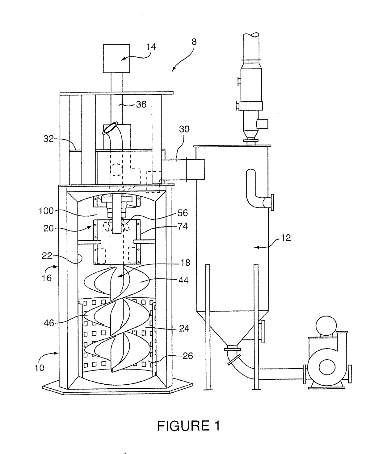
[0023]Reference may be had to FIG. 1 which illustrates a lime slaking apparatus 8 used in the production of slaked lime in accordance with a preferred embodiment. The slaking apparatus 8 includes a vertical ball mill 10 and separator 12. As will be described, the vertical ball mill 10 is used in conjunction with a number of hardened stainless steel grinding balls 11 in the grinding and mixture of calcium oxide as an input mineral with water to produce a slaked lime slurry. Most preferably, calcium oxide is initially fed into the ball mill 10 having an average particle diameter of from several millimetres to less than 10 cm, and preferably in pebble form with a diameter less than 6.4 cm. The ball mill 10 in turn, is fluidically coupled to the separator 12 and which is used to reduce the water content in the produced slurry to the desired final water to lime ratio.

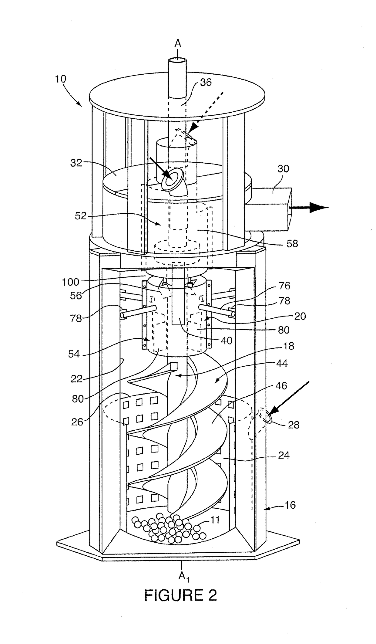
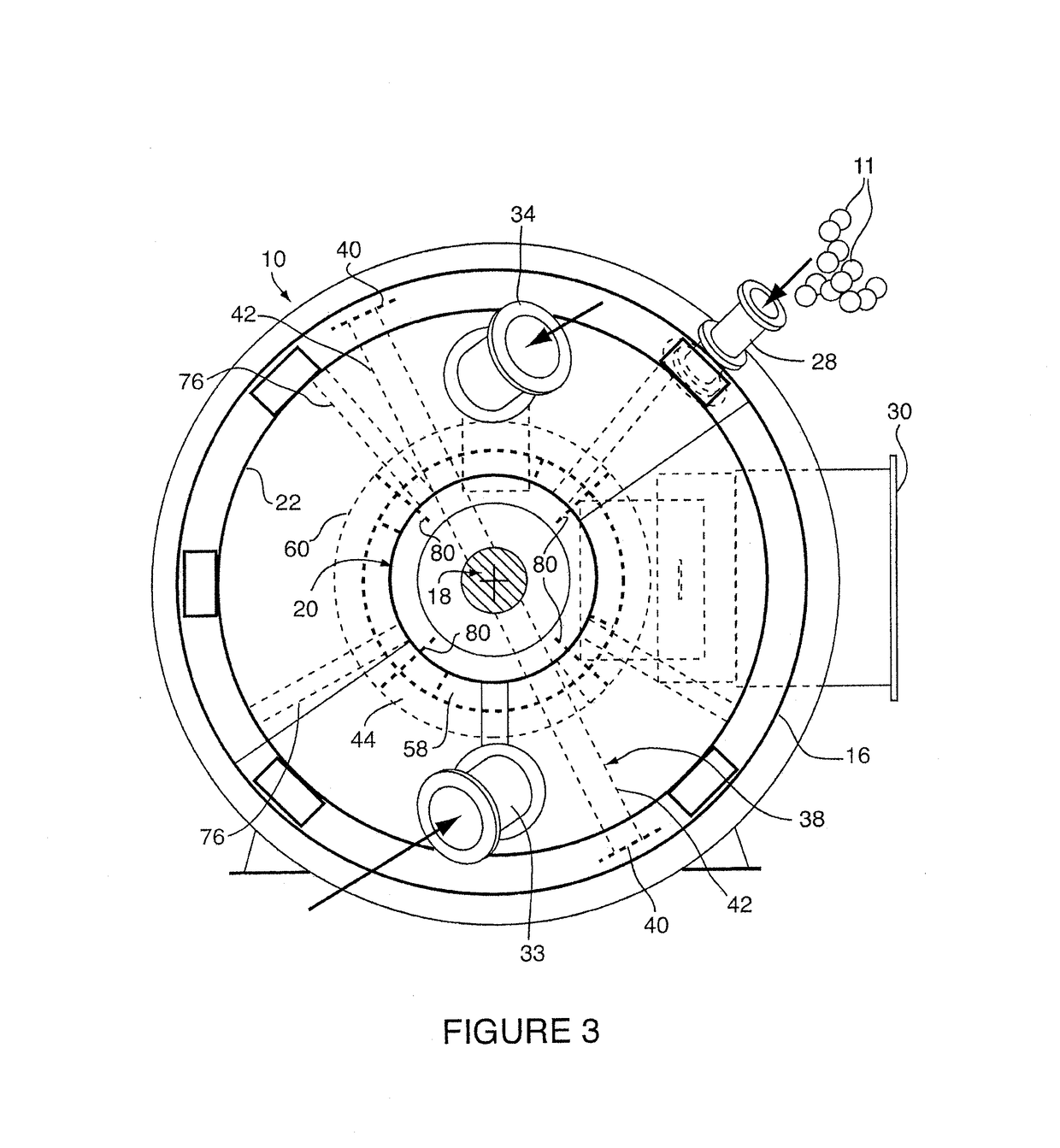
[0024]FIGS. 2 and 3 show best the vertical ball mill 10 used in the lime slaking apparatus 8 of FIG. 1. The ball mill 10 i...


PUM


Abstract

A vertical ball mill for grinding a solid input material to form a slurry, and includes a grinding tank which defines a mixing chamber, rotatable main auger assembly having mixing blade in a lower portion of the mixing chamber and a materials flow guide. The flow conduit is provided within the grinding tank interior, and includes one or more conduit segments configured to direct input material downwardly in the grinding tank towards the lower mixing chamber and auger mixing blade. An impeller is provided within the flow conduit, with a blade configuration selected to effect the downward flow of input material through the conduit segments and outwardly therefrom adjacent to the mixing blade as the auger assembly is rotated.

Description

SCOPE OF THE INVENTION[0001]The present invention relates to vertical grinding mills, and more particularly vertical ball mills which incorporate an internal flow baffle, guide or conduit for directing the flow of input materials towards a lower region of the mill grinding / mixing chamber.BACKGROUND OF THE INVENTION[0002]Vertical grinding mills are widely used in industrial process applications in the reduction and / or pulverization of ore, rock, minerals and other input materials for subsequent processing in mining applications, as well as for example, in the manufacture of fertilizers, cement, glass and ceramics. Conventionally, vertical grinding mills are provided with a grinding tank which is adapted to receive both a volume of solution and the material to be ground or pulverized as either part of a batch or continuous process. An impeller assembly is provided with a mixing or grinding blade which is positioned in a lower region of the grinding tank. When rotated, the mixing blade...

Claims


Application Information

Patent Timeline
Patent Type & Authority Applications(United States)
IPC IPC(8): B02C17/16B02C17/00
CPCB02C17/00B02C17/163B02C17/16B02C17/02
Inventor BORGES, TYLERFANG, XIAOQI STEPHENNG, CHIEN-EESARBAN, CALIN
Owner STORAGE & TRANSFER TECH INC
Why Eureka
Try Eureka