Air assisted fuel injector

a fuel injector and air technology, applied in the direction of liquid fuel feeders, machines/engines, lighting and heating apparatus, etc., can solve the problems of affecting the fuel flow from the fuel injector, affecting the spray targeting, etc., and achieves accurate targeting, low cost, and good atomization

Inactive Publication Date: 2000-10-17
FORD GLOBAL TECH LLC
View PDF19 Cites 4 Cited by
  • Summary
  • Abstract
  • Description
  • Claims
  • Application Information

AI Technical Summary

Benefits of technology

An advantage of the present invention is that low cost air assist fuel injector having good atomization and accurate targeting is provided.
Another advantage of the present invention is that the fuel injector and engine utilizing the injector may be easily manufactured.
Other objections, features and advantages of the present invention will be readily appreciated by the reader of this specification.
The invention will now be described, by way of example, with reference to the accompanying drawings in which:
FIG. 1 is a side view of an air assisted fuel injector according to the present invention;
According to the present invention, air assist shroud 30 further includes throttling section 40 disposed upstream of targeting section 38. Throttling section 40 comprises recess 42 formed on inside surface 35 of sidewall 34 and extends along the axial direction of shroud 30. Recess 42 has a generally converging cross-section, constricting the air to thereby throttle the air flowing through air shroud 30, as will become further apparent with reference to FIGS. 7-9. Air shroud 30 further includes air port 44 for communicating with air assist port 24 of cylinder head 20. By providing throttling section 40 upstream of targeting section 38, any adverse effects on fuel flow from injector 10 due to back pressure variability downstream of nozzle 16 are reduced. Further, by providing a gradual decreasing cross-section of throttling section 40, assist air having a more laminar flow with reduced edge effects may be provided. This reduces the likelihood of a mismatched spray distribution flowing from targeting section 38 at partial engine manifold pressures (i.e., at pressures less than at wide open throttle). The throttling section 40 further comprises an offset angled portion, preferably in the form of a helix, within the cross section of the throttling section 40. Thus, as the throttling section 40 extends axially toward the tip 18 of the injector, the throttling section 40 extends circumferentially to provide an angled passage 43, preferably in the form of a helix. Preferably a pair of diametrically opposed passages are provided, whereby the helical or angled passages 43 generate a vortex at the discharge point, thereby improving fuel atomization.

Problems solved by technology

However, assist air in such air assisted fuel injectors tends to disrupt any spray targeting which may be performed by the fuel injector.
This restriction may adversely effect fuel flow from the fuel injector due to back pressure variability downstream of the fuel nozzle.
This is inconvenient due to the proximity of the fuel discharge point to the intake valve of the engine.

Method used


Image

  • Air assisted fuel injector
  • Air assisted fuel injector
  • Air assisted fuel injector

Examples


Embodiment Construction

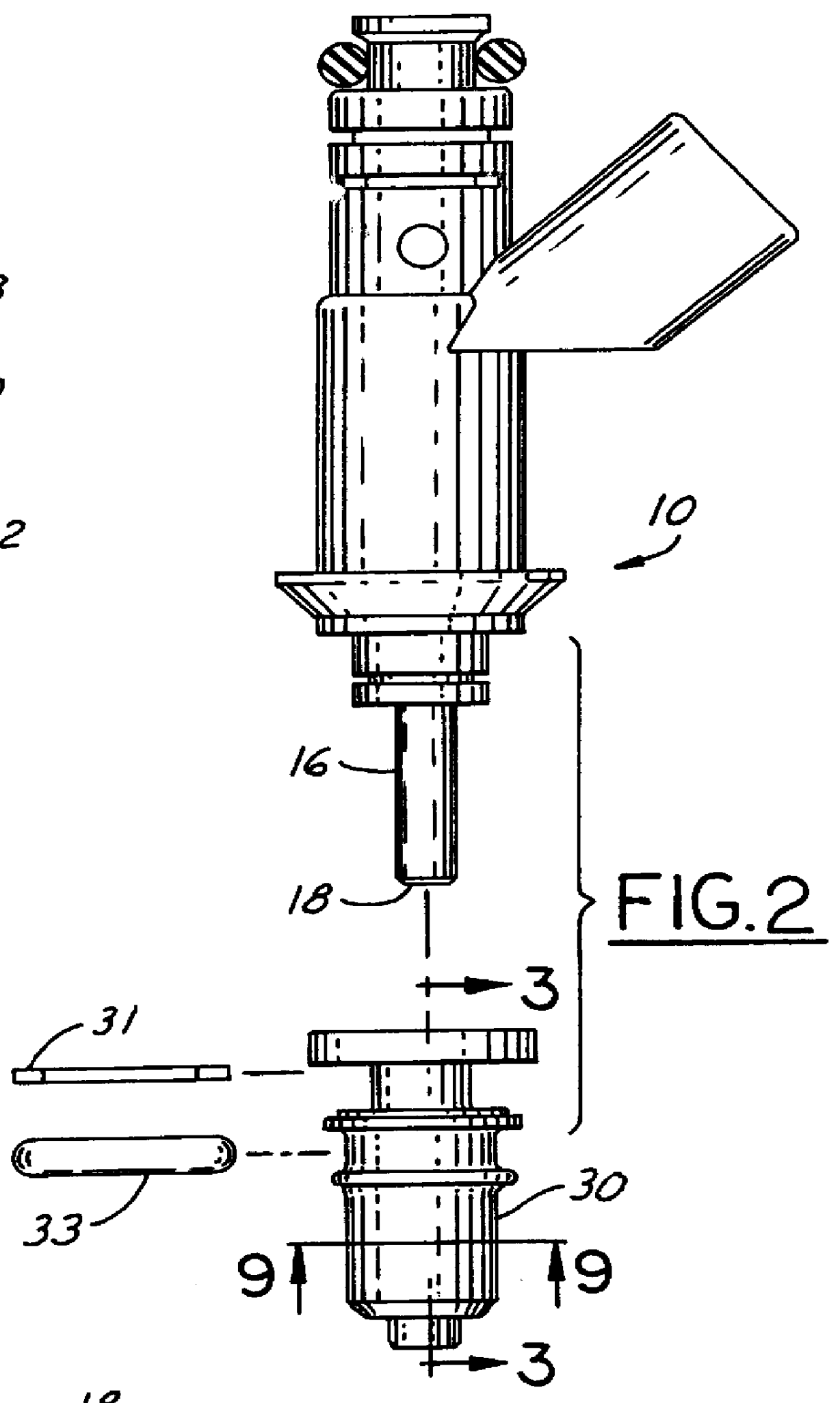
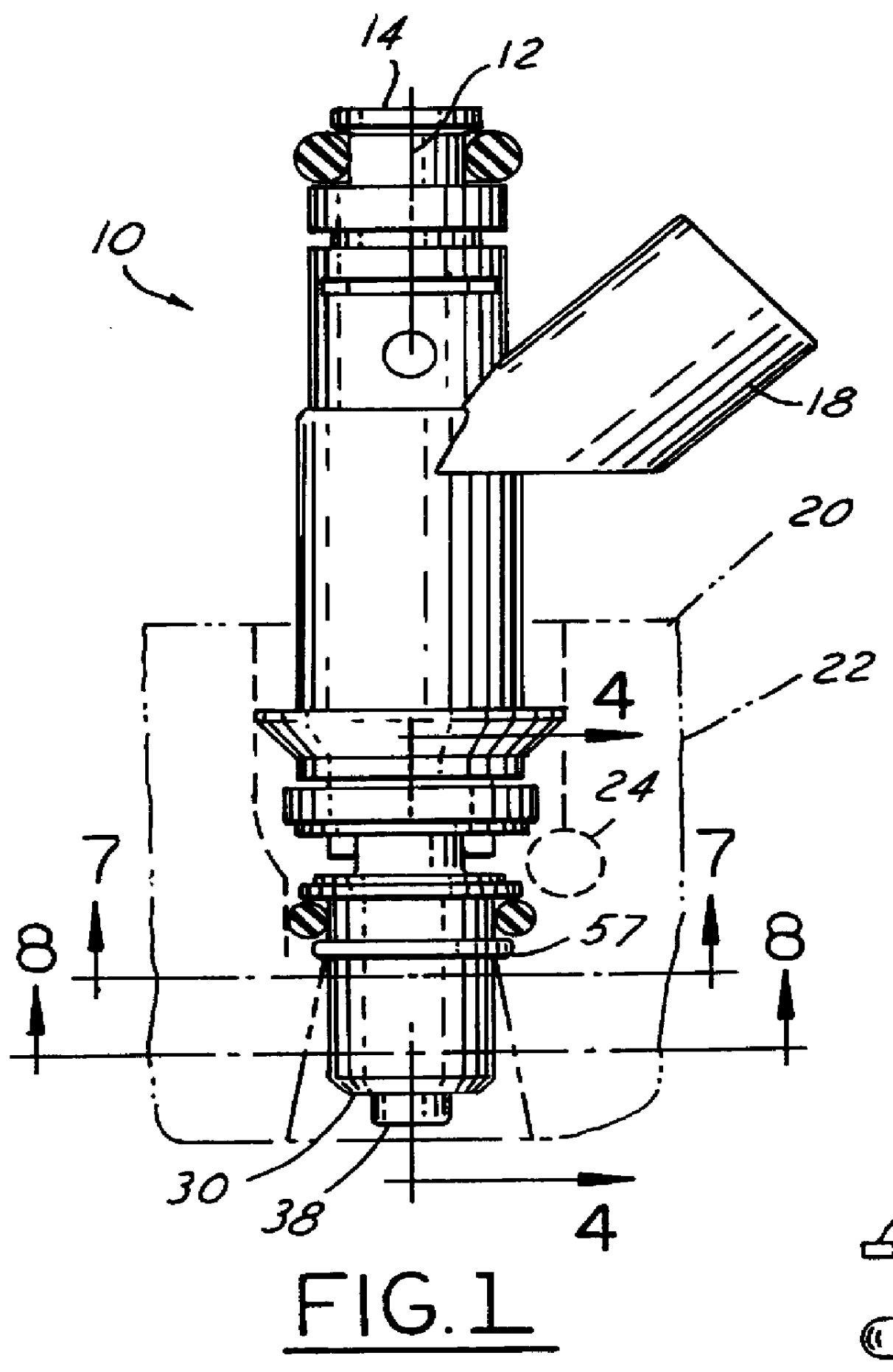
Air assisted fuel injector 10, shown in FIGS. 1 and 2, which, in this example, is a top feed fuel injector, includes central longitudinal axis 12 with inlet 14 and nozzle 16 (see FIG. 2) at its opposite axial ends. Liquid fuel is dispensed by the operation of a conventional solenoid actuated needle valve (not shown) contained within fuel injection 10, which receives its signals from an engine controller (not shown) through fuel injector connector 18. Typically, fuel is delivered from a fuel rail (not shown) to inlet 14 and is controlled by the aforementioned solenoid valve. Fuel injector 10 is fitted within cylinder head 20 of internal combustion engine 22 to deliver fuel thereto. Alternatively, those skilled in the art will recognize in view of this disclosure that fuel injector 10 may be fitted to an intake manifold (not shown). For the sake of clarity, in the example described herein, fuel injector 10 is mounted to cylinder head 20. Engines utilizing air assisted fuel injectors a...


PUM


Abstract

An air assisted fuel injector for an internal combustion engine includes a fuel nozzle having a fuel orifice and a targeting section cooperating with the fuel nozzle for targeting atomized fuel within the engine. An angled throttling section in disposed upstream of the targeting section and cooperates with the fuel nozzle. The throttling section throttles assist air prior to the air atomizing the fuel emerging from the fuel orifice and forms a vortex at the injector exit. Thus, any adverse effects on fuel flow from the fuel injector due to back pressure variability downstream of the fuel nozzle are reduced. In a preferred embodiment, an air shroud is fitted on the nozzle of the fuel injector and includes both the throttling section and the targeting section.

Description

This invention relates to air assisted fuel injectors, and, more particularly to, throttling assist air in such fuel injectors.BACKGROUND OF INVENTIONAir assisted fuel injectors for automotive internal combustion engines take advantage of the natural air flow in an engine, due to manifold vacuum, to better atomize fuel spray, which, in turn, is known to improve combustion and efficiently reduce exhaust emissions. Typically, the engine includes an assist air passage which communicates with the fuel injector for providing assist air to the nozzle of the fuel injector for atomization. It is also known to use fuel injectors which target the fuel spray within the engine. However, assist air in such air assisted fuel injectors tends to disrupt any spray targeting which may be performed by the fuel injector.European Patent Application #EP740,069 ('069) shows an air assisted fuel injector having an air shroud placed on the nozzle of the injector. Assist air is directed to the fuel spray as ...

Claims


Application Information

Patent Timeline
Patent Type & Authority Patents(United States)
IPC IPC(8): F02M61/00F02M61/16F02M69/04
CPCF02M69/047F02M61/162
Inventor FLY, RON G.
Owner FORD GLOBAL TECH LLC
Why Eureka
Try Eureka