Cabinent apparatus and cabinet light assembly

a cabinet light and cabinet technology, applied in the direction of instruments, lighting support devices, built-in power, etc., can solve the problems of inconvenient retrieval or placement of items in cabinets, lack of illumination devices in most cabinets, etc., and achieve the effect of better illumination

Active Publication Date: 2017-06-22
LEEDARSON IOT TECH INC
View PDF2 Cites 2 Cited by
  • Summary
  • Abstract
  • Description
  • Claims
  • Application Information

AI Technical Summary

Benefits of technology

[0006]In an example, the illumination device may be implemented with an LED strip and a light guide plate. The light guide plate may be made of plastic plate or other material and / or structures that guide light emitted from the LED strip to inner space of the cabinet body. With light guide plate, the light source is more smooth and reaching more widely in the inner space of the cabinet body.
[0007]In an example, the LED strip is placed in the inner portion of the cabinet body. The light guide plate has more light refraction points near the LED strip. As mentioned above, the light guide plate helps direct light emitted from the LED strip to different places in the cabinet body. One of light guiding design is to use refraction. Multiple light transmission path may be implemented on the light guide plate and there are multiple light exiting points on the light guide plate. In one example, there are more light exiting points close to the inner side of the cabinet body than the outer side of the cabinet body. Because it is usually darker in the inner side the cabinet, such design provides better illumination for the inner side of the cabinet body.
[0008]In another example, the conductive rail has a plurality of predetermined positions to be chosen by a user for engaging the conductive terminal to one of the predetermined positions to adjust an illumination effect of the illumination device in the cabinet body.

Problems solved by technology

Most cabinets, however, do not have illumination devices.
Also, because of illuminating angles, the inside space of cabinets appears darker, making people inconvenient to retrieve or place items in cabinets.

Method used


Image

  • Cabinent apparatus and cabinet light assembly
  • Cabinent apparatus and cabinet light assembly
  • Cabinent apparatus and cabinet light assembly

Examples


Embodiment Construction

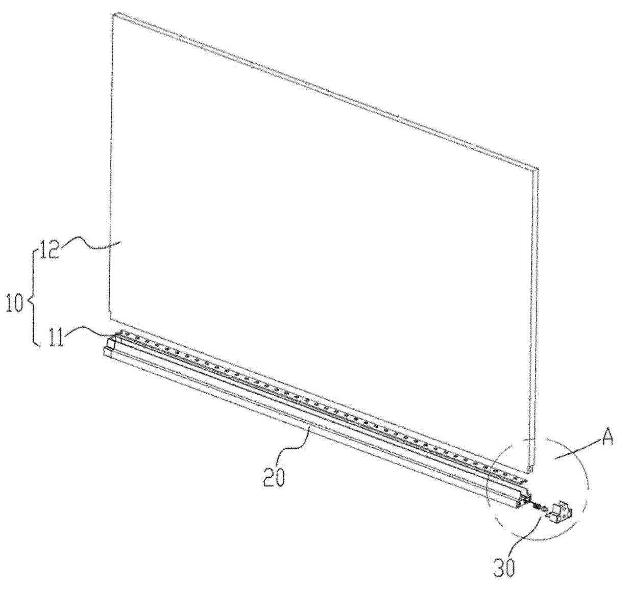
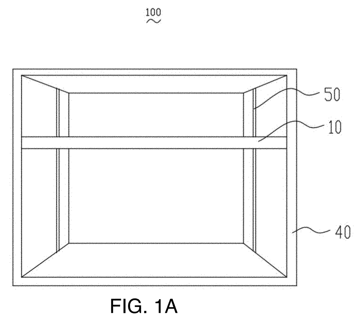
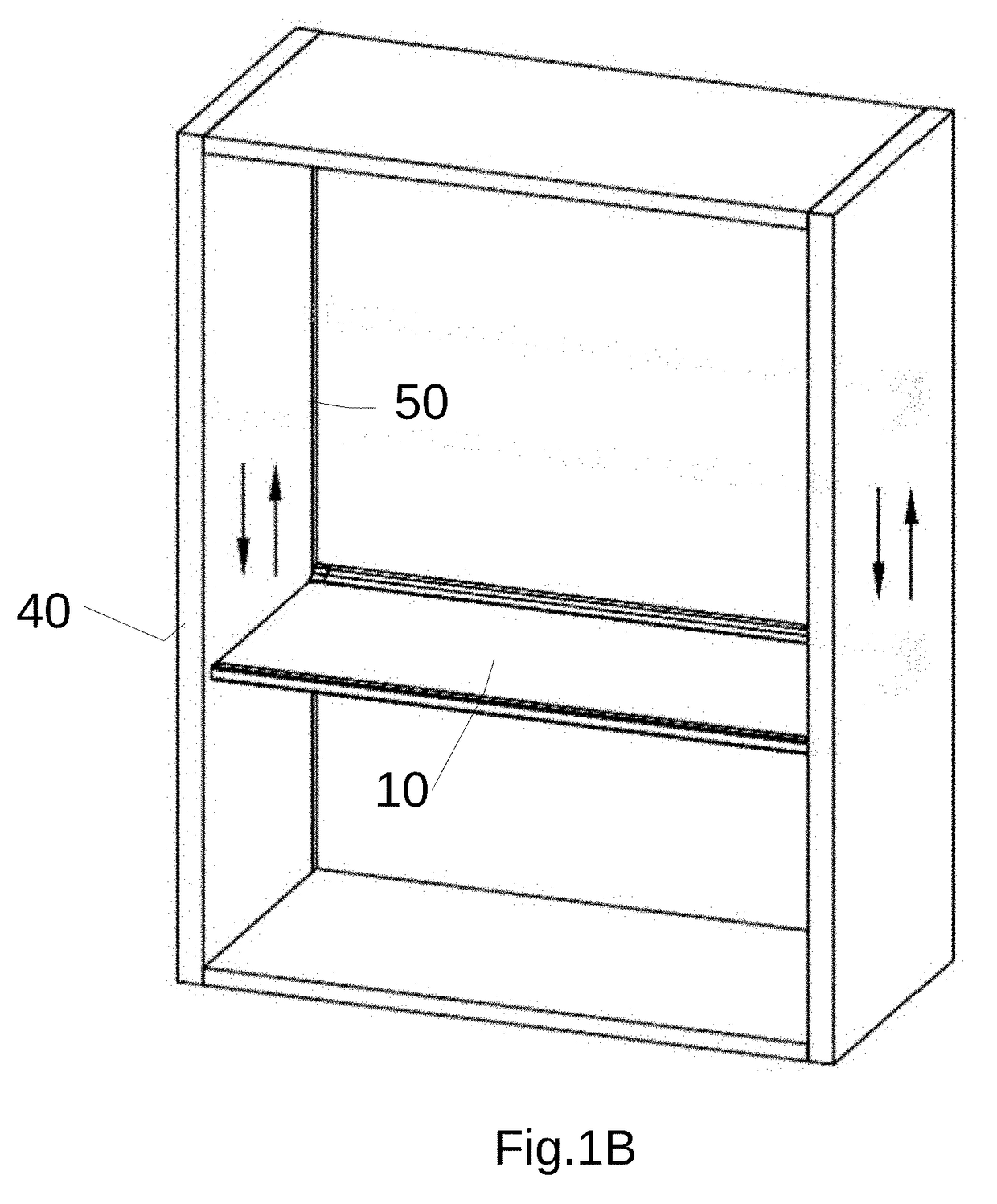
[0048]Please refer to FIG. 8. According to an embodiment of the present invention, a cabinet apparatus includes a cabinet body 801, a conductive rail 804, an illumination device 802 and a conductive terminal 803. The conductive rail 804 is disposed inside the cabinet body 801. The conductive rail 804 is connected to a power supply (not shown). The conductive terminal 803 is connected to the illumination device 802 and the conductive rail 804. The conductive terminal 803 is adjustable to elastically engage the conductive rail 804 for conducting electricity from the power supply to the illumination device 802.

[0049]In an example, the cabinet may be a wardrobe, a cupboard, a drawer or other containers. The illumination device 802 may be an LED (Light Emitting Diode) based illumination device that may contain one or more than one LED dies connected in series or in other manner. The conductive rail 804 may be a metal strip mounted in the cabinet body 801 via sticking, screws or other man...


PUM


Abstract

A cabinet light includes a light emitting element, a light housing, conductive terminals, a cabinet body, and conductive rails. The light emitting element and the conductive terminals are fixed on the light housing. The conductive rails are fixed on the cabinet body. One end of the conductive terminal is electrically connected to the light emitting element. At least one positioning element is disposed on the cabinet body corresponding to the light housing. When the light housing is fixed on the cabinet body through the positioning element, the other end of the conductive terminal is elastically and electrically connected to the conductive rail. The cabinet body has advantages of simple wiring and use flexibility.

Description

FIELD OF INVENTION[0001]The present invention relates to a cabinet apparatus and a cabinet light assembly and more particularly relates to an adjustable cabinet apparatus and an adjustable cabinet light assembly.BACKGROUND[0002]Cabinets are square, rectangular or other geometry shape storage devices for storing daily use items like closing and document files, and are widely found everywhere. Cabinets may be classified into wardrobes, cupboards, drawers, etc. Most cabinets, however, do not have illumination devices. Without illumination, users rely on lights emitted from outside of windows or electric lights in the room to recognize and to take items from cabinets. Also, because of illuminating angles, the inside space of cabinets appears darker, making people inconvenient to retrieve or place items in cabinets. For cupboards with more fragile items such as dishes stored inside, it is easy for users to break fragile items therein. Thus, there is a need to provide better illumination ...

Claims


Application Information

Patent Timeline
Patent Type & Authority Applications(United States)
IPC IPC(8): F21V33/00F21S4/28F21S9/02F21V8/00
CPCF21V33/0012G02B6/0068F21S4/28F21Y2105/10F21W2131/301F21Y2115/10F21S9/02F21S8/00F21V21/35F21V23/04A47B97/00A47B2220/0077A47F11/10F21Y2105/00G02B6/0038G02B6/0061G02B6/0065G02B6/0078G02B6/0095
Inventor ZHONG, NIYANGLI, WEIZHONGZHENG, SHENGFANG
Owner LEEDARSON IOT TECH INC
Why Eureka
Try Eureka