Vehicle

a technology for vehicles and headlamps, applied in the field of vehicles, can solve the problems of difficult irradiation of front regions by head lamps in the traveling direction, and achieve the effects of increasing the change rate of luminosity of light emitted, preventing rapid change in light intensity, and increasing the change over time of postur

Active Publication Date: 2017-06-29
KAWASAKI MOTORS LTD
View PDF4 Cites 12 Cited by
  • Summary
  • Abstract
  • Description
  • Claims
  • Application Information

AI Technical Summary

Benefits of technology

[0025]In accordance with this configuration, since the luminosity of the light emitted from the auxiliary lamp is gradually increased with an increase in the bank angle from the timing at which the auxiliary lamp starts to be lighted, a rapid change in the luminosity of the light can be prevented. This makes it possible to prevent, for example, a situation in which the rider feels discomfort due to abrupt lighting of the auxiliary lamp.
[0026]The control section may increase a change rate of luminosity of light emitted from the auxiliary lamp with respect to a bank angle of the vehicle body, with an increase in the change over time of the posture of the vehicle body in the direction in which the vehicle body is banked to the first side in the vehicle w

Problems solved by technology

In other words, it becomes difficult for the head lamp to irradiate a front region in the traveling direction which is

Method used


Image

  • Vehicle
  • Vehicle
  • Vehicle

Examples


embodiment 1

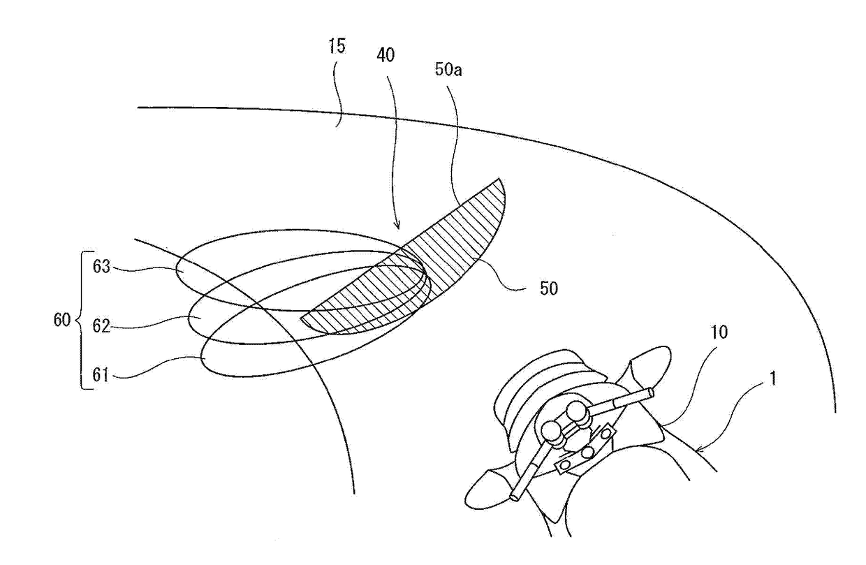
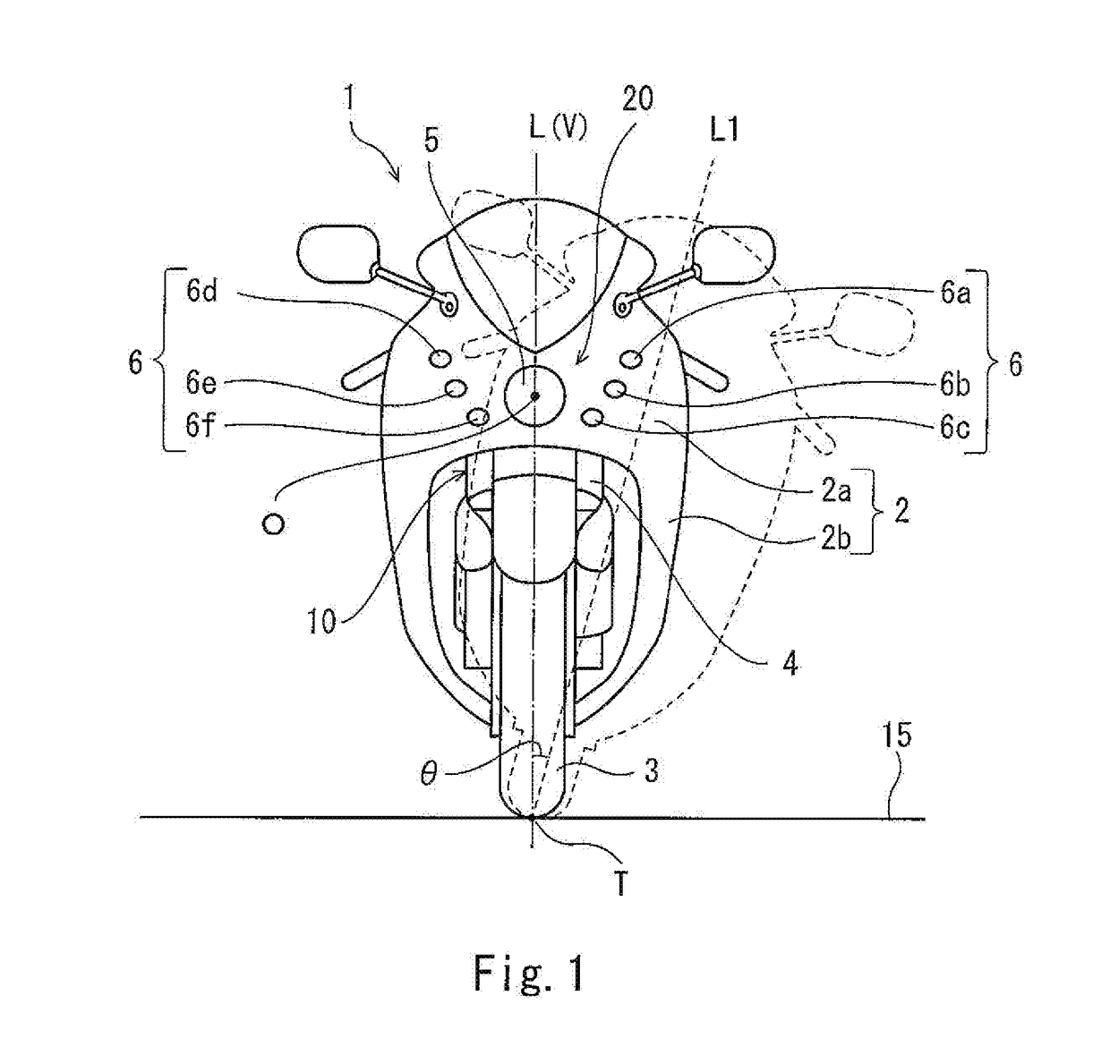
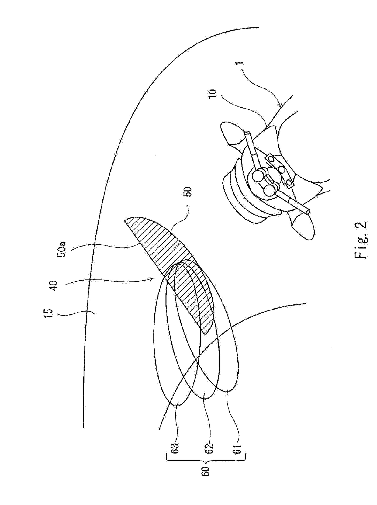
[0047]FIG. 1 is a front view of a motorcycle 1 according to Embodiment 1. As shown in FIG. 1, the motorcycle 1 includes a cowling 2 covering a vehicle body 10. The cowling 2 includes a front cowling 2a, and a side cowling 2b. A front fork 4 is rotatably coupled at a lower end portion thereof to a front wheel 3. The front cowling 2a covers the upper side of the front fork 4. The side cowling 2b is located rearward relative to the front cowling 2a and covers the vehicle body 10 from outer sides in the vehicle width direction.

[0048]A lamp 20 including a head lamp 5 and a plurality of auxiliary lamps 6 is attached to the front portion of the front cowling 2a. In the present embodiment, the head lamp 5 is a head lamp including a light emitting diode (LED) light source as a light source. The light source of the head lamp 5 is not limited to the LED light source, and may be a halogen lamp, a discharge lamp, etc.

[0049]The plurality of auxiliary lamps 6 are attached to the vehicle body 10 on...

embodiment 2

[0095]In the motorcycle according to Embodiment 2, the control for the lighting operations of the auxiliary lamps 6 according to Embodiment 1 is modified. Hereinafter, regarding the control for the lighting operations of the auxiliary lamps 6 according to Embodiment 2, differences from the control for the lighting operations of the auxiliary lamps 6 according to Embodiment 1 will be described.

[0096]Hereinafter, a case where the control for the lighting operation according to Embodiment 2 is performed for the first auxiliary lamp 6a will described. FIG. 6A is a view showing the control performed for the lighting operation of the first auxiliary lamp 6a according to Embodiment 2, corresponding to FIG. 4. As shown in FIG. 6A, in Embodiment 2, the change rate of the luminosity of the light emitted from the first auxiliary lamp 6a, with respect to the bank angle, is changed based on the bank angular velocity. Specifically, the change rate of the luminosity of the light emitted from the f...

embodiment 3

[0101]In the motorcycle according to Embodiment 3, the control for the lighting operations of the auxiliary lamps 6 according to Embodiment 1 is modified. Hereinafter, regarding the control for the lighting operations of the auxiliary lamps 6 according to Embodiment 3, differences from the control for the lighting operations of the auxiliary lamps 6 according to Embodiment 1 will be described.

[0102]In a case where the auxiliary lamp 6 starts to be lighted when the vehicle body 10 is banked at the set bank angle, the light is not emitted to the front region in the traveling direction before the auxiliary lamp 6 starts to be lighted. Or, in a case where the auxiliary lamp 6 is lighted abruptly at the set bank angle, the rider feels discomfort.

[0103]In the present embodiment, the lighting state of each of the auxiliary lamps 6 includes a preceding lighting state and a set lighting state which are different in luminosity depending on the value of the bank angle. The preceding lighting s...


PUM


Abstract

A vehicle which turns in a state in which a vehicle body is banked from an upright state to a first side in a vehicle width direction of the vehicle body, comprises a lamp which is attached to the vehicle body, and irradiates a lamp irradiation region set in front of the vehicle body; a detecting section which detects a change over time of a posture of the vehicle body while the vehicle is traveling; and a control section which controls the lamp in such a manner that the lamp irradiation region is changed based on the change over time of the posture of the vehicle body which is detected by the detecting section.

Description

CROSS-REFERENCE TO THE RELATED APPLICATION[0001]This application claims priority to and the benefit of Japanese Patent Application No. 2015-256648 filed on Dec. 28, 2015, the entire disclosure of which is incorporated herein by reference.BACKGROUND OF THE INVENTION[0002]Field of the Invention[0003]The present invention relates to a vehicle which turns in a state in which its vehicle body is banked (tilted) from an upright state to one side in a vehicle width direction.[0004]Description of the Related Art[0005]In some cases, an exemplary vehicle such as a motorcycle turns in a state in which its vehicle body is banked while the vehicle is traveling. The vehicle is provided with a head lamp to secure a rider's view irrespective of whether or not the vehicle body is banked. For example, in a case where the vehicle turns in a state in which its vehicle body is banked from an upright state to the left, a region to be irradiated by the head lamp is lowered at the left from the perspective...

Claims


Application Information

Patent Timeline
IPC IPC(8): B60Q1/10H05B37/02B60Q1/18F21S8/10B62J6/02B60Q1/00
CPCB60Q1/10B62J6/02B60Q1/0041B60Q1/18B60Q2300/054F21S48/1721H05B37/0227B60Q2300/136F21S48/1225B60Q1/12B62J6/023B62J45/4151F21S41/285F21S41/635H05B47/115Y02B20/40
Inventor SAKAMOTO, TAKUYAIWAMOTO, TAROTANI, OSAMU
Owner KAWASAKI MOTORS LTD
Why Eureka
Try Eureka