Battery module

a battery module and battery technology, applied in the field of battery modules, can solve the problems of poor pressure resistance ability of the end plate fixed on the substrate, degradation of battery module performance, poor end plate rigidity, etc., and achieve the effects of poor intermediate mechanical properties, and increasing the rigidity of the end pla

Active Publication Date: 2017-10-26
CONTEMPORARY AMPEREX TECH CO
View PDF0 Cites 5 Cited by
  • Summary
  • Abstract
  • Description
  • Claims
  • Application Information

AI Technical Summary

Benefits of technology

[0023](1) Since the curling pipe section and the end plate are an integral structure which does not need additional connecting sleeve members, the problem of poor intermediate mechanical properties caused by the connecting procedures of different components is avoided, moreover, since the curling pipe section is a curved-surface structure which helps to disperse the vertical pressure coming from the side plates, when confronting the external pressure, the end plate is more resistant of pressure.
[0024](2) The curling pipe section on the end plate also plays a role as the ribbed plate, which increases the rigidity of the end plate, so as to prevent the end plate fro...

Problems solved by technology

After the power battery modules are installed on an electric vehicle, adverse external factors for the modules such as shaking and vibration and the like will occur to the electric vehicle during the driving process, if the battery modules are not fixed at a specific position, the battery modules are readily damaged due to the impact, collision and extrusion between the battery modules caused by relative displacement between the battery modules, over time the battery module performance will deteriorate or lose efficacy, in a severe case, safety accidents s...

Method used


Image

  • Battery module
  • Battery module
  • Battery module

Examples


Embodiment Construction

[0048]In order to make the objects, technical solutions and advantages of the present application more clear, the technical solutions of the present application are clearly and completely described combining the embodiments and accompanying drawings of the present application, obviously, the embodiments described are merely a part of the embodiments of the present application but not all of the embodiments. Based on the technical solutions and the embodiments provided by the present application, all other embodiments obtained by persons skilled in the art without any creative efforts shall belong to the protection scope of the present application.

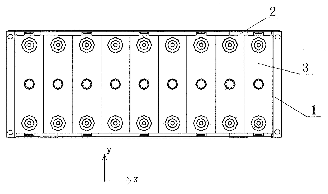
[0049]The “length”, “width” and “height” in the disclosure refer to the placement state of the cell 3 (battery unit) in the drawings.

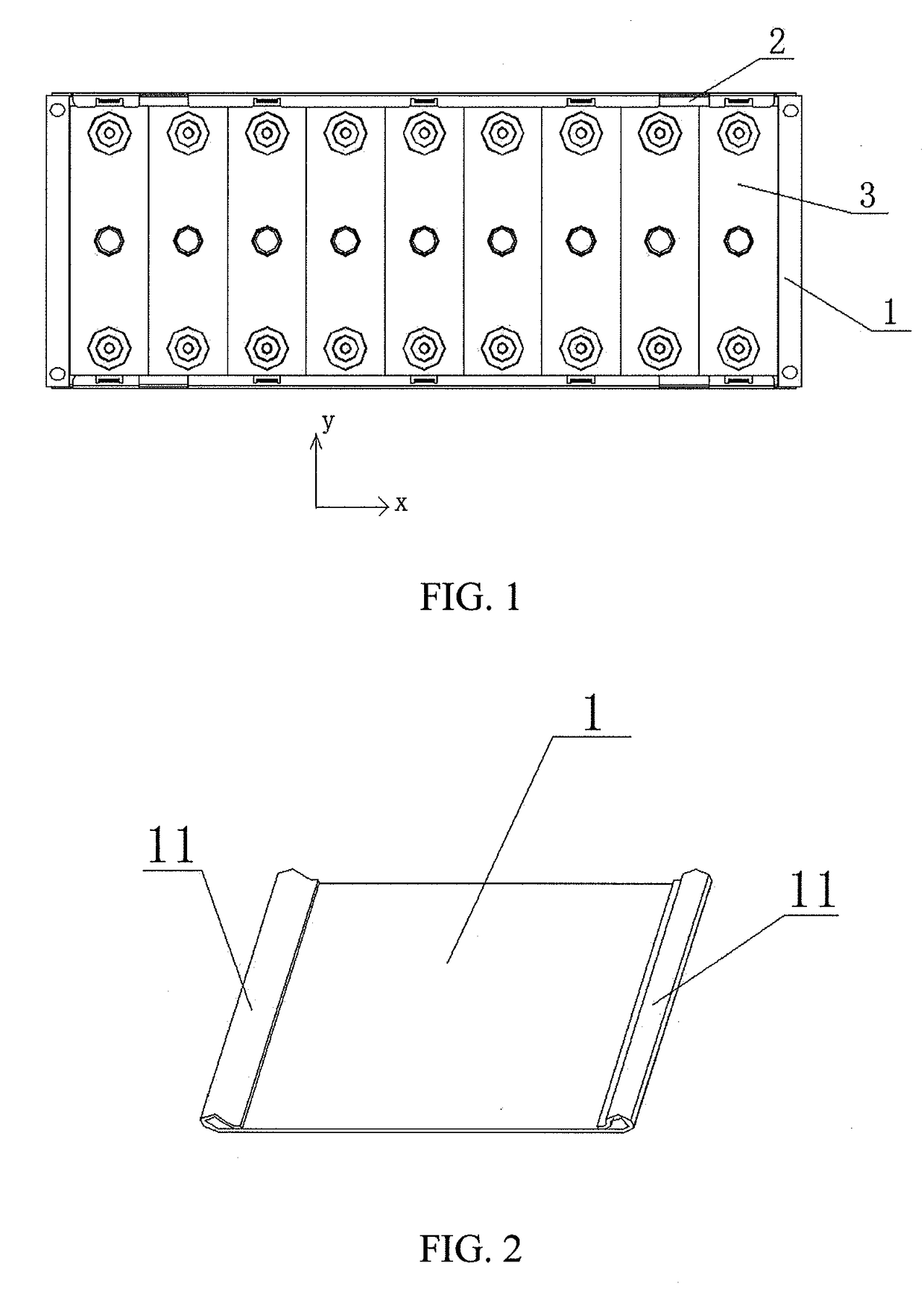
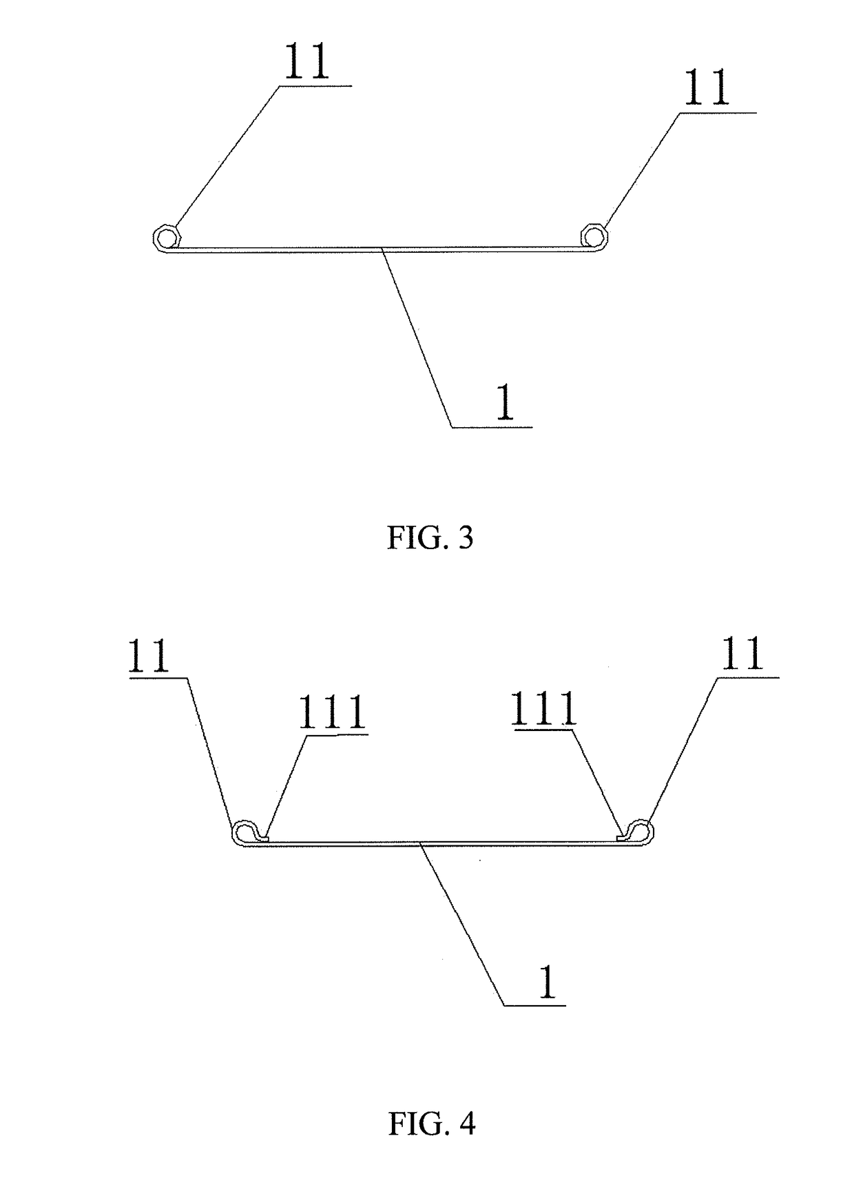
[0050]A battery module, as shown in FIG. 1, including a substrate (located at the bottom of the cell 3, not shown), a plurality of cells 3, a pair of end plates 1, a pair of side plates 2 and a plurality of fa...


PUM


Abstract

This application relates to a battery module, including a substrate, battery units, end plates, side plates and fastening pieces; the end plates are respectively located on two sides of the battery units in their stacking direction, adjacent to outermost ones of the battery units and extend along a length direction of the battery unit; an end of the end plate in the length direction is curled into a pipe and forms a curling pipe section, an axial direction of the curling pipe section is the same with a height direction of the battery unit; the fastening piece is inserted in the curling pipe section, extends in the curling pipe section toward the substrate and protrudes out of the curling pipe section, and are fixed on the substrate; by configuring curling pipe sections, fastening strength is improved, so as to realize reliable fixation of the battery module on the substrate.

Description

CROSS-REFERENCE TO RELATED APPLICATIONS[0001]The present application claims priority to Chinese Patent Application No. 201610250992.2, filed on Apr. 21, 2016, the content of which is incorporated herein by reference in its entirety.TECHNICAL FIELD[0002]The present application relates to the technical field of energy storage devices and, particularly, relates to a battery module.BACKGROUND[0003]After the power battery modules are installed on an electric vehicle, adverse external factors for the modules such as shaking and vibration and the like will occur to the electric vehicle during the driving process, if the battery modules are not fixed at a specific position, the battery modules are readily damaged due to the impact, collision and extrusion between the battery modules caused by relative displacement between the battery modules, over time the battery module performance will deteriorate or lose efficacy, in a severe case, safety accidents such as short circuit, fire and the lik...

Claims


Application Information

Patent Timeline
IPC IPC(8): H01M2/10H01M50/204H01M50/229H01M50/249H01M50/264
CPCH01M2/1094H01M2220/20H01M2/1077H01M50/229H01M50/264H01M50/204H01M10/0481Y02E60/10Y02P70/50H01M50/24
Inventor WU, ANWEIZHAO, BINYAO, QIONGWEIZHONG, GUANGYUELUO, SICHUANCHEN, YONGCHENG
Owner CONTEMPORARY AMPEREX TECH CO
Why Eureka
Try Eureka