Circuit device, electronic device, physical quantity sensor, and vehicle

a technology of electronic devices and circuit devices, applied in pulse manipulation, pulse techniques, instruments, etc., can solve problems such as and achieve the effect of suppressing the deterioration of the determination accuracy of the comparator

Active Publication Date: 2018-04-26
SEIKO EPSON CORP
View PDF0 Cites 0 Cited by
  • Summary
  • Abstract
  • Description
  • Claims
  • Application Information

AI Technical Summary

Benefits of technology

The solution effectively suppresses determination accuracy deterioration and reduces power consumption by converting voltage differences into time information for digital processing, enabling accurate signal comparison and A / D conversion even at low voltage differences.

Problems solved by technology

In general, in a case where a voltage difference between a voltage input to a positive terminal of a comparator and a voltage input to a negative terminal is a predetermined voltage or less, determination accuracy of the comparator may be deteriorated.

Method used


Image

  • Circuit device, electronic device, physical quantity sensor, and vehicle
  • Circuit device, electronic device, physical quantity sensor, and vehicle
  • Circuit device, electronic device, physical quantity sensor, and vehicle

Examples


Embodiment Construction

[0052]Hereinafter, preferred embodiments of the invention will be described in detail. It is to be noted that the embodiment described below does not unduly limit the contents of the invention described in the appended claims, and not all of the configurations described in the embodiment are necessarily indispensable as solutions of the invention.

1. Overview

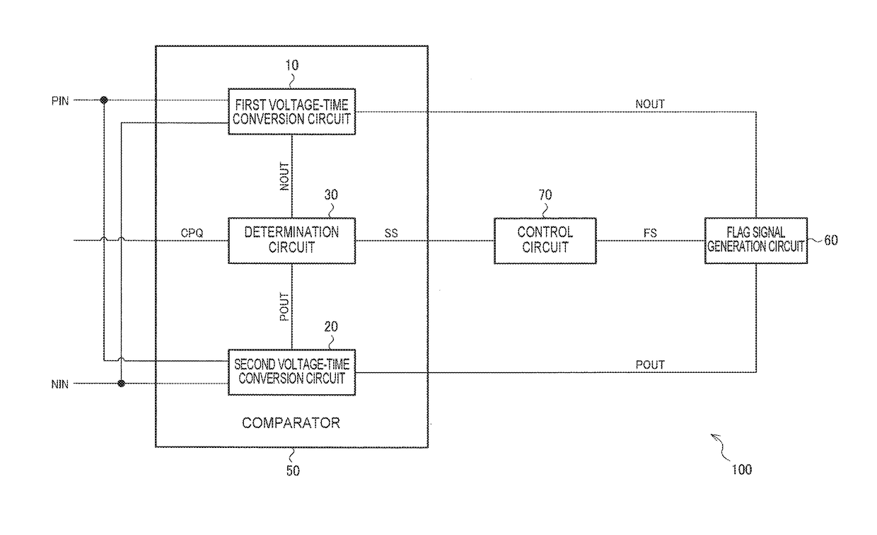
[0053]FIG. 1 shows a circuit configuration diagram of a circuit device 100 of the embodiment. The circuit device 100 of the embodiment includes a comparator 50 which performs a comparison operation of input signals, and a flag signal generation circuit 60 which generates a flag signal used for controlling the comparison operation.

[0054]The comparator 50 includes a first voltage-time conversion circuit 10, a second voltage-time conversion circuit 20, and a determination circuit 30.

[0055]The first voltage-time conversion circuit 10 receives at least a first input signal PIN and outputs a first time information signal NOUT. The seco...


PUM


Abstract

A circuit device includes a comparator and a flag signal generation circuit. The comparator includes a first voltage-time conversion circuit to which at least a first input signal is input and which outputs a first time information signal, a second voltage-time conversion circuit to which at least a second input signal is input and which outputs a second time information signal, and a determination circuit that determines magnitude relation of the first input signal and the second input signal, based on the first time information signal and the second time information signal. The flag signal generation circuit generates a flag signal indicating that a voltage difference between the first input signal and the second input signal is a predetermined voltage or less, based on the first time information signal and the second time information signal.

Description

CROSS-REFERENCE TO RELATED APPLICATIONS[0001]This application is a continuation of U.S. patent application Ser. No. 15 / 656,449, filed Jul. 21, 2017, which claims priority to Japanese Patent Application No. 2016-145094, filed Jul. 25, 2016, both of which are hereby expressly incorporated by reference herein in their entireties.BACKGROUND1. Technical Field[0002]The present invention relates to a circuit device, an electronic device, a physical quantity sensor, a vehicle, or the like.2. Related Art[0003]A time-domain type comparator is known which converts an input voltage level into a time (for example, a delay time of a signal edge, a pulse width of a pulse signal, a period of a clock signal, or the like), and performs comparison of the input voltage level by comparison of the time.[0004]For example, U.S. Pat. No. 8,373,444 discloses a time domain-type comparator, and a sequential comparison-type A / D converter using it. The time domain-type comparator of U.S. Pat. No. 8,373,444 inclu...

Claims


Application Information

Patent Timeline
Patent Type & AuthorityApplications(United States)
IPC IPC(8): H03K5/24H03M1/50G01C5/00G01C19/5776G05D1/08
CPCG05D1/08G01C5/005H03K5/24H03M1/50G01C19/5776H03M1/38H03K5/26H03K2005/00032
InventorHANEDA, HIDEO
OwnerSEIKO EPSON CORP