Indicator of the Opening and/or Closing Status of a Tap or a Pressure Reducer

Active Publication Date: 2018-10-25
ROTAREX SA
View PDF7 Cites 2 Cited by
  • Summary
  • Abstract
  • Description
  • Claims
  • Application Information

AI Technical Summary

Benefits of technology

[0023]The invention is particularly interesting in that it provides a useful and reliable indication of the status of a device such as a tap, a valve or a pressure reducer. The indication can been easily seen by an operator located at any position around the longitudinal axis of the device. Also, the use of the rotor and of a track on said rotor provides a large freedom for controlling the position of the indicator sleeve relative to the angular position of the spindle. Also the indicato

Problems solved by technology

It shows however as drawback that the position of the indicator

Method used


Image

  • Indicator of the Opening and/or Closing Status of a Tap or a Pressure Reducer
  • Indicator of the Opening and/or Closing Status of a Tap or a Pressure Reducer
  • Indicator of the Opening and/or Closing Status of a Tap or a Pressure Reducer

Examples


Embodiment Construction

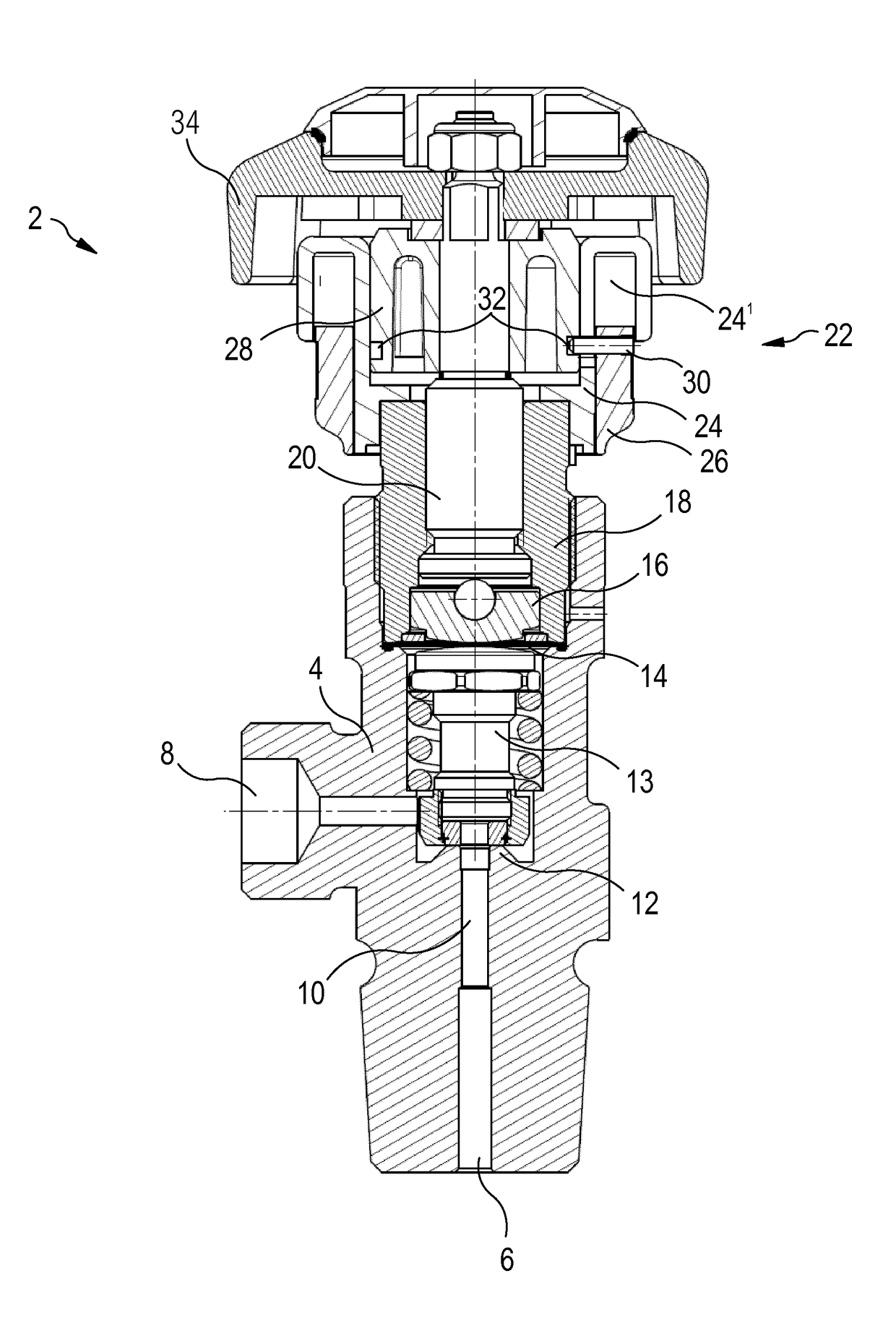
[0033]FIG. 1 is a cross-sectional view of a shut-off valve or tap for gas cylinders, equipped with an indicator of the opening and / or closing status in accordance with the invention.

[0034]The tap 2 comprises a body 4 with an inlet 6, an outlet and a passage 10 fluidly connecting the inlet 6 with the outlet 8. In the passage 10 there is provided a seat 12, around said passage, and a closure member 13 for cooperating the seat 12 in a gas tight fashion. To that end, the tap 2 comprises a pressure element 16 that is configured for exerting a pressure on the movable closure member 13, via a membrane 14, towards the seat 12. When such a pressure is exerted, the membrane 14 deforms and the closure member 13 moves to contact the seat 12 and shuts-off the passage through said seat 12, thereby shutting-off the passage and the fluid flow.

[0035]The tap 2 comprises a gland ring 18 that presses an outer annular area of the membrane 14 against a supporting surface in the body 4 in order to provide...


PUM


Abstract

The invention is directed to an indicator (22) of the opening and/or closing status of a device controlling the flow of a fluid, such as a tap or a pressure reducer for compressed gas, comprising a sleeve-shaped support (24) to rotatably engage with a protruding portion (18) of a body of the device and from which an actuating spindle (20) extends along a longitudinal axis of said device; an indicator sleeve (26) axially sliding along the support (24); a rotor (28) to be fixed to the spindle (20) and comprising at its periphery a least one track (32) with a curved profile; and at least one track follower (30) extending radially from the indicator sleeve (26) through a longitudinal slot (242) in the support (24) and engaging with the at least one track (32).

Description

TECHNICAL FIELD[0001]The invention is directed to the field of devices for controlling the flow of a fluid, like a compressed gas. These devices can be taps or pressure reducers. More particularly, the invention is directed to the indication of the status of such devices.BACKGROUND ART[0002]Prior art patent document published US 2005 / 0139268 A1 discloses a tap for gas cylinder and with a position indicator. The latter is mounted between a cylindrical portion of the tap body and the actuating wheel of the tap. The position indicator comprises, essentially, a sleeved-shaped support slip on the cylindrical portion of the tap body and an indicator sleeve with an inner thread engaging with an outer thread on the support. The indicator sleeve is also in rotational engagement with the actuating wheel of the tap. The sleeve-shaped support comprises a signalling end portion that can be covered and uncovered by the indicator sleeve. During operation of the tap, when rotating the actuating whe...

Claims


Application Information

Patent Timeline
IPC IPC(8): F16K37/00F16K1/30
CPCF16K37/0008F16K1/302Y10T137/8275Y10T137/8225
Inventor CHIR, PASCALMUZZO, PAULSCHMITZ, JEAN-CLAUDE
Owner ROTAREX SA
Why Eureka
Try Eureka