Pneumatic brake booster having a recessed bearing surface

Active Publication Date: 2018-07-05
CONTINENTAL TEVES AG & CO OHG
View PDF13 Cites 0 Cited by
  • Summary
  • Abstract
  • Description
  • Claims
  • Application Information

AI Technical Summary

Benefits of technology

[0007]An aspect of the invention is based on offering an improved brake booster whi

Problems solved by technology

The tooling costs are not increased b

Method used


Image

  • Pneumatic brake booster having a recessed bearing surface
  • Pneumatic brake booster having a recessed bearing surface
  • Pneumatic brake booster having a recessed bearing surface

Examples


Embodiment Construction

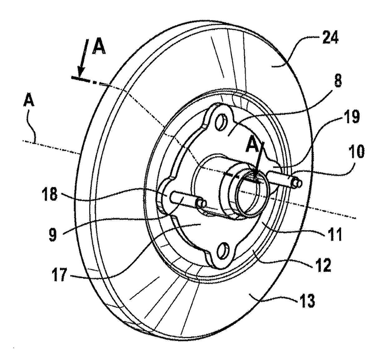
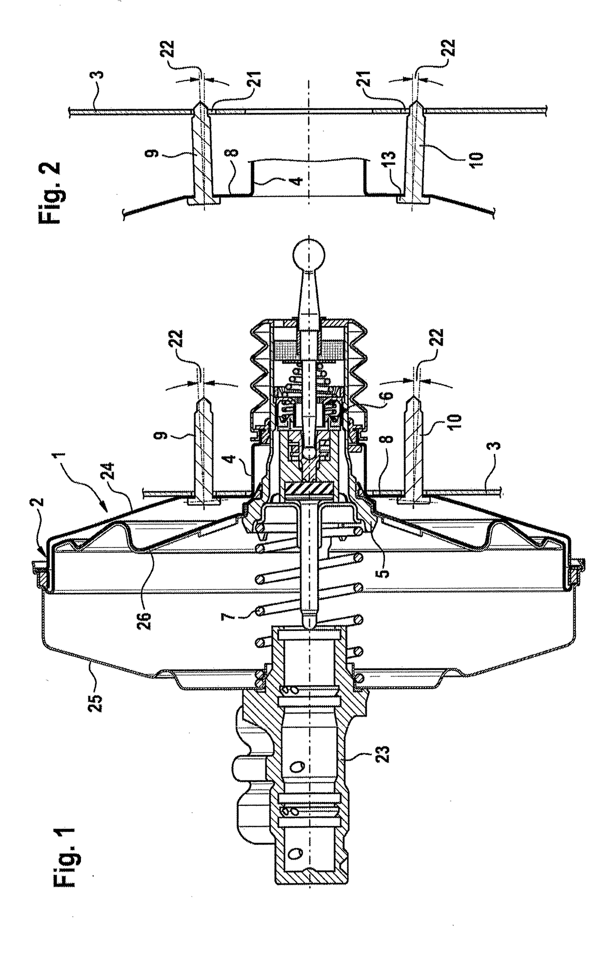
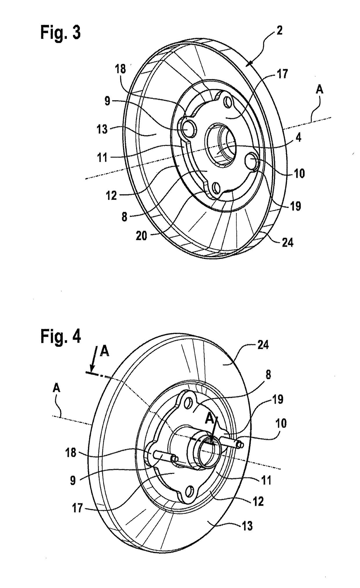
[0021]A known pneumatic brake booster 1, which is presented in FIG. 1, has a booster housing 2 which can be attached, on its side illustrated on the right here, to a vehicle body part 3. On the opposite side, the housing of a master brake cylinder 23 is illustrated. The booster housing 2 comprises two housing shells—a rear housing shell 24 on the vehicle body side and its front housing shell 25 on the master brake cylinder side, which housing shell shells 24, 25 are arranged in series axially along the central axis A and connected to one another. In addition to the illustrated single brake booster, the invention can also extend to a tandem brake booster.

[0022]The rear housing shell 24 of the booster housing 2 forms a central tube 4 which extends axially outward in the direction of the vehicle body part 3. An axially shiftable control housing 5 with a valve arrangement 6 which is accommodated therein and controls the brake booster 1 is partially arranged in the tube 4. An axially mov...


PUM


Abstract

In order to minimize spreading, without additional parts, of connecting bolts of a pneumatic brake booster in a manner which is brought about by the deformation of a bearing surface on a booster housing before and during its assembly on a provided vehicle body part, it is proposed that the bearing surface is assigned a planar surface section in an immediately adjacent manner which is configured so as to be plane-parallel with respect to the bearing surface and so as to be axially inwardly recessed on the booster housing with a circumferential step.

Description

CROSS REFERENCE TO RELATED APPLICATIONS[0001]This application is the U.S. National Phase Application of PCT International Application No. PCT / EP2016 / 066114, filed Jul. 7, 2016, which claims priority to German Patent Application No. 10 2015 212 986.1, filed Jul. 10, 2015, the contents of such applications being incorporated by reference herein.FIELD OF THE INVENTION[0002]The invention relates to a pneumatically operating brake booster for a hydraulic motor vehicle brake system.BACKGROUND OF THE INVENTION[0003]Brake boosters of this type are widespread and are generally attached to a vehicle body part—usually the splash wall—in the engine compartment of a vehicle by means of two or more connecting bolts. For efficient mounting, the connecting elements are secured on or in the housing of the brake booster. During the mounting of the brake booster, the above-mentioned connecting elements are plugged through corresponding breakthroughs in the vehicle body part and are secured from the op...

Claims


Application Information

Patent Timeline
IPC IPC(8): B60T13/567B60T13/52
CPCB60T13/567B60T13/52B60Y2400/81
Inventor FALLER, JURGENMUNIZ, JULIANOLADEIRA, GUSTAVOGAIOTTO, FABIOIDERIHA, MARCELOARAUJO, FABIO
Owner CONTINENTAL TEVES AG & CO OHG
Why Eureka
Try Eureka