Cleaner

Pending Publication Date: 2021-08-05
LG ELECTRONICS INC
View PDF6 Cites 1 Cited by
  • Summary
  • Abstract
  • Description
  • Claims
  • Application Information

AI Technical Summary

Benefits of technology

[0009]A first object of the present disclosure is to provide a cleaner with

Problems solved by technology

According to the related art, since the dust sensor is mounted on a pipe far away from the main body, a structure for connecting power from the main body is required, resulting in problems such as a complicated structure, an increased manufacturing

Method used


Image

  • Cleaner
  • Cleaner
  • Cleaner

Examples


Embodiment Construction

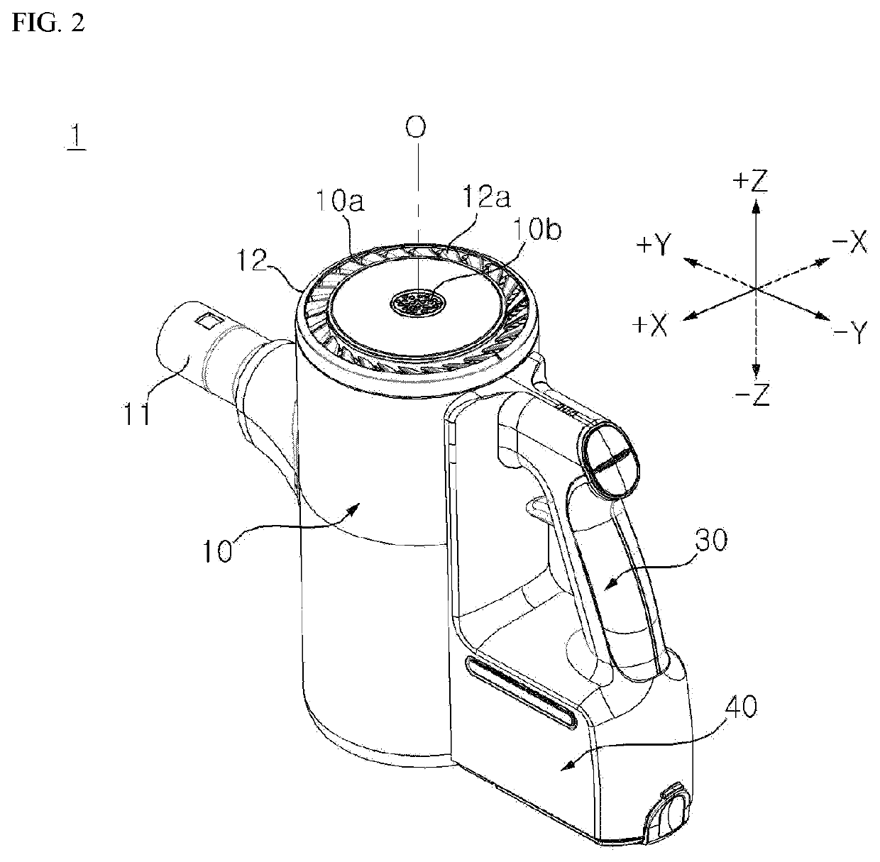
[0049]The present disclosure will be described below based on a spatial Cartesian coordinate system formed by the X-axis, Y-axis, and Z-axis that are orthogonal to each other. Each axial direction (X-axis direction, Y-axis direction, Z-axis direction) means both directions in which each axis extends. A ‘+’ sign in front of each axis direction (+X-axis direction, +Y-axis direction, +Z-axis direction) means a positive direction, which is one of both directions in which each axis extends. A ‘−’ sign in front of each axis direction (−X-axis direction, −Y-axis direction, −Z-axis direction) means a negative direction, which is the other of both directions in which each axis extends.

[0050]Although expressions designating directions such as “front (+Y) / rear (−Y) / left (+X) / right (−X) / up (+Z) / down (−Z)” mentioned below is defined according to the XYZ coordinate axis, these are simply given to explain the present disclosure for clear understanding, and it is obvious that the respective directi...


PUM


Abstract

Provided is a cleaner including a dust separation unit separating dust in the air, a suction flow path supplying outside air to the dust separation unit, a fan module moving the air in the suction flow path, and a dust sensor measuring concentration of dust in the suction flow path. The suction flow path includes a first suction flow path extending in a first direction and a second suction flow path connecting the first suction flow path to the dust separation unit and extending in a second direction that forms an obtuse angle with the first direction, and the dust sensor is disposed in the second suction flow path.

Description

CROSS-REFERENCE TO RELATED APPLICATIONS[0001]This application claims priority to and the benefit of Korean Patent Application No. 10-2020-0013375, filed on Feb. 4, 2020. The disclosure of the prior application is incorporated by reference in its entirety.BACKGROUND OF THE DISCLOSUREField of the Disclosure[0002]The present disclosure relates to an arrangement of a dust sensor in a cleaner.Related Art[0003]Cleaners may be classified into a manual cleaner for cleaning while a user directly moves the cleaner, and a robot cleaner for cleaning while traveling by itself. In addition, the manual cleaner may be classified into a canister-type cleaner, an upright-type cleaner, a handy-type cleaner, a stick-type cleaner, or the like, depending on the shape of the cleaner.[0004]The cleaner includes an impeller and a suction motor for rotating the impeller to provide the driving force to suck in dust.[0005]In the related art, a dust sensor is mounted for measuring the concentration of dust in th...

Claims


Application Information

Patent Timeline
IPC IPC(8): A47L9/28A47L5/24
CPCA47L9/2815A47L9/1641A47L5/24A47L9/281A47L9/1616A47L9/1625A47L9/1683A47L9/22A47L9/165A47L9/0072A47L9/2842
Inventor LEE, DONGJAERYU, JUNGWANCHANG, DAEHOYANG, JAESUNG
Owner LG ELECTRONICS INC
Why Eureka
Try Eureka