Device for fastening trackside modules to rails

Active Publication Date: 2019-08-13
BOMBARDIER TRANSPORTATION ZWUS POLSKA
View PDF14 Cites 0 Cited by
  • Summary
  • Abstract
  • Description
  • Claims
  • Application Information

AI Technical Summary

Benefits of technology

[0017]Since the at least one upwardly extending section is fastened to the bracket or brackets, the mounting of the trackside module to the section or sections is easy and re-positioning of the section or sections relative to the clamp is possible without the need to loosen the fixation of the clamp on the rail. In particular, re-positioning is possible by loosening th

Problems solved by technology

Both at the stage of installation and of normal operation it is required to perform initial and periodical adjustment of the position

Method used


Image

  • Device for fastening trackside modules to rails
  • Device for fastening trackside modules to rails
  • Device for fastening trackside modules to rails

Examples


example of an embodiment

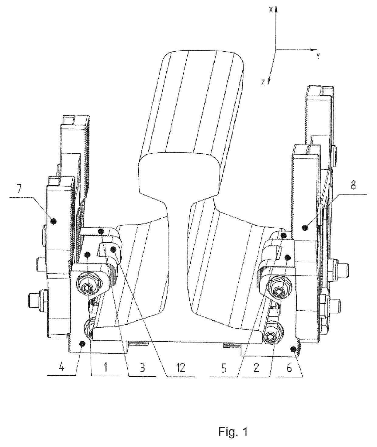
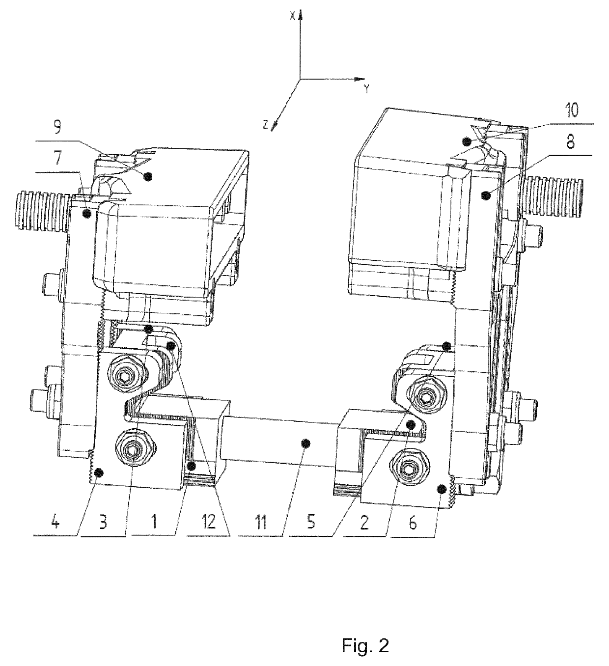
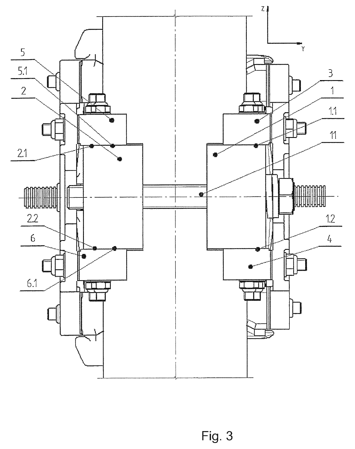
[0033]The movable clamps 1, 2 of the device which are clamped on the base of a rail are in the form of supports with brackets 3, 4, 5, 6 that are fastened to the side surfaces of supports. Clamping of the clamps 1, 2 on the base of a rail is possible thanks to the use of threaded fasteners 11 which are led via the clamps 1, 2 and under the base of the rail. The brackets 3, 4, 5 and 6 do not touch the base of the rail. The purpose of the brackets 3 and 4 is to hold the vertical section 7 together with a trackside module 9 in the required position. The change of position of brackets 3, 4 in parallel to the Y axis enables changing the position of the trackside module in parallel to Y axis.

[0034]The change of position of sections 7 in relation to brackets 3, 4 in parallel to X axis makes it possible to change the position of the trackside module 9 in parallel to X axis.

[0035]The purpose of brackets 5 and 6 is to hold the vertical section 8 together with a trackside module 10 in the requ...


PUM


Abstract

The invention relates to a device for fastening trackside modules to a rail having a base and a head. The device includes two clamps that are clamped on the base of the rail with the use of a mechanism that extends under the base of the rail. At least one of the clamps is movable. A bracket is fastened to at least one of the clamps and a trackside module is fastened next to the head of the rail. A pair of brackets is fastened with the use of fasteners to surfaces of each of the clamps. The brackets extend transversely to the longitudinal axis of the rail and at least one upwardly extending section is fastened using second fasteners to at least one of the brackets outer side surfaces. At least one trackside module is fastened to an upper end region of at least one upwardly extending section.

Description

CROSS-REFERENCE TO RELATED APPLICATIONS[0001]This application is the United States national phase of International Application No. PCT / EP2016 / 061129 filed May 18, 2016, and claims priority to Polish Patent Application No. P.412382 filed May 18, 2015, the disclosures of which are hereby incorporated in their entirety by reference.BACKGROUND OF THE INVENTIONField of the Invention[0002]The invention relates to a device for fastening trackside modules, in particular to a running rail of a railway for rail vehicles. For example, the rail may be a grooved rail and / or a Vignole type rail). In particular the rail may be one of the two rails of a dual-rail railway for rail vehicles. In particular, one or more than one of the following devices are examples of trackside modules to be fastened to the rail: wheel and / or vehicle detectors, in particular wheel detector heads, current transformers and communication devices for communication between a vehicle travelling on the rail and the trackside...

Claims


Application Information

Patent Timeline
IPC IPC(8): E01B9/32E01B26/00B61L1/16B61L1/02B61L3/22B61L3/12
CPCE01B9/32B61L1/02B61L1/16E01B26/00B61L3/22B61L2003/228B61L3/126
Inventor GÓRNIOCZEK, MAREKRADWANSKI, WOJCIECHSZCZEPONIK, ADAMZIELINSKI, DARIUSZMAZUR, MATEUSZSTEPIEN, ANDRZEJSAWODNI, ALEKSANDRA
Owner BOMBARDIER TRANSPORTATION ZWUS POLSKA
Why Eureka
Try Eureka