Pneumatic Tire

a technology of pneumatic tires and rubber bands, which is applied in the field of pneumatic tires, can solve the problems of tire noise, high-speed durability degradation, and problems such as deformation of elastic fixed bands, and achieve the effects of reducing the damage of the band-like sound absorption member caused by tire strain, promoting heat dissipation, and improving the high-speed durability of pneumatic tires

Active Publication Date: 2018-11-01
YOKOHAMA RUBBER CO LTD
View PDF0 Cites 2 Cited by
  • Summary
  • Abstract
  • Description
  • Claims
  • Application Information

AI Technical Summary

Benefits of technology

[0009]A depth d of the cuts is preferably 50% with regard to a thickness D of the band-like sound absorbing member. Thereby, the cuts on an end portion of the band-like sound absorbing member can open when cornering to promote heat dissipation from the band-like sound absorbing member and improve high-speed durability of the pneumatic tire. Furthermore, damaging of the band-like sound absorbing member caused by tire strain can be effectively suppressed.
[0010]A volume of the band-like sound absorbing member is preferably 10% to 30% with regard to the luminal volume of the tire. Thereby, a sound absorbing effect based on the band-like sound absorbing member can be even further achieved. An excellent noise reducing effect can be achieved by increasing the volume of the band-like sound absorbing member, and a favorable stress relieving effect and heating dissipating effect can be demonstrated even with a large band-like sound absorbing member. The luminal volume of the tire is a volume of a cavity portion formed between a tire and rim in a condition where the tire is mounted on a regular rim and inflated to a regular internal pressure “Regular rim” is a rim defined by a standard for each tire according to a system of standards that includes standards on which tir

Problems solved by technology

Cavernous resonance caused by the vibration of the air filled in a cavity portion of a tire is one cause of tire noise.
However, if securing the sound absorbing member is dependent on the elastic fixed band, problems occur where the elastic fixed band deforms during high speed travel.
However, in this case, the band-like sound absorbing member is directly applied to a tire inner sur

Method used


Image

  • Pneumatic Tire
  • Pneumatic Tire
  • Pneumatic Tire

Examples


examples

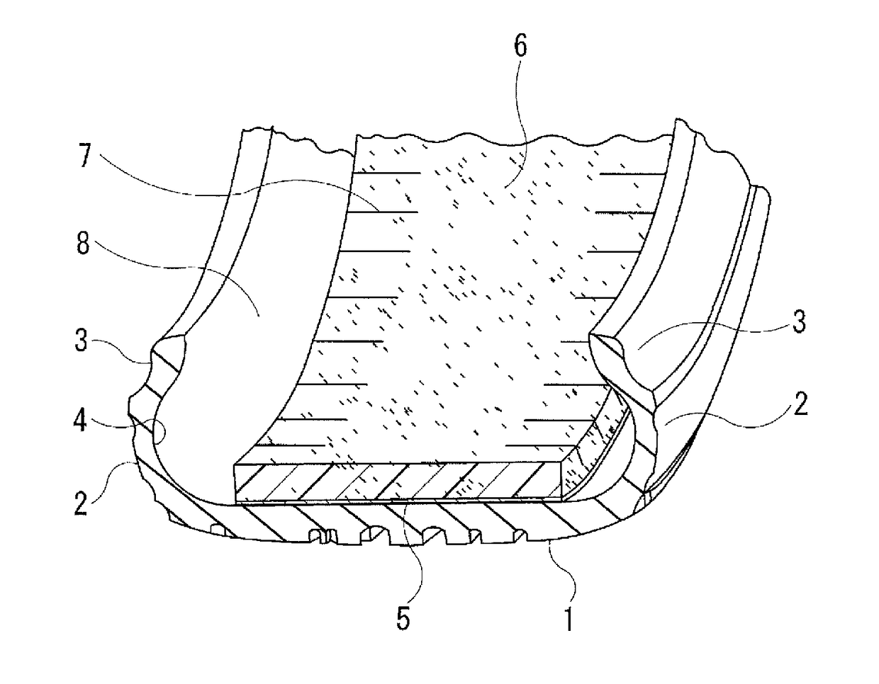
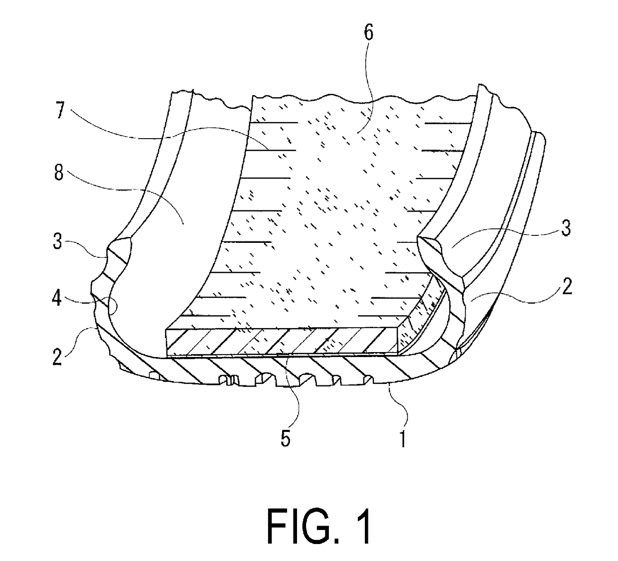
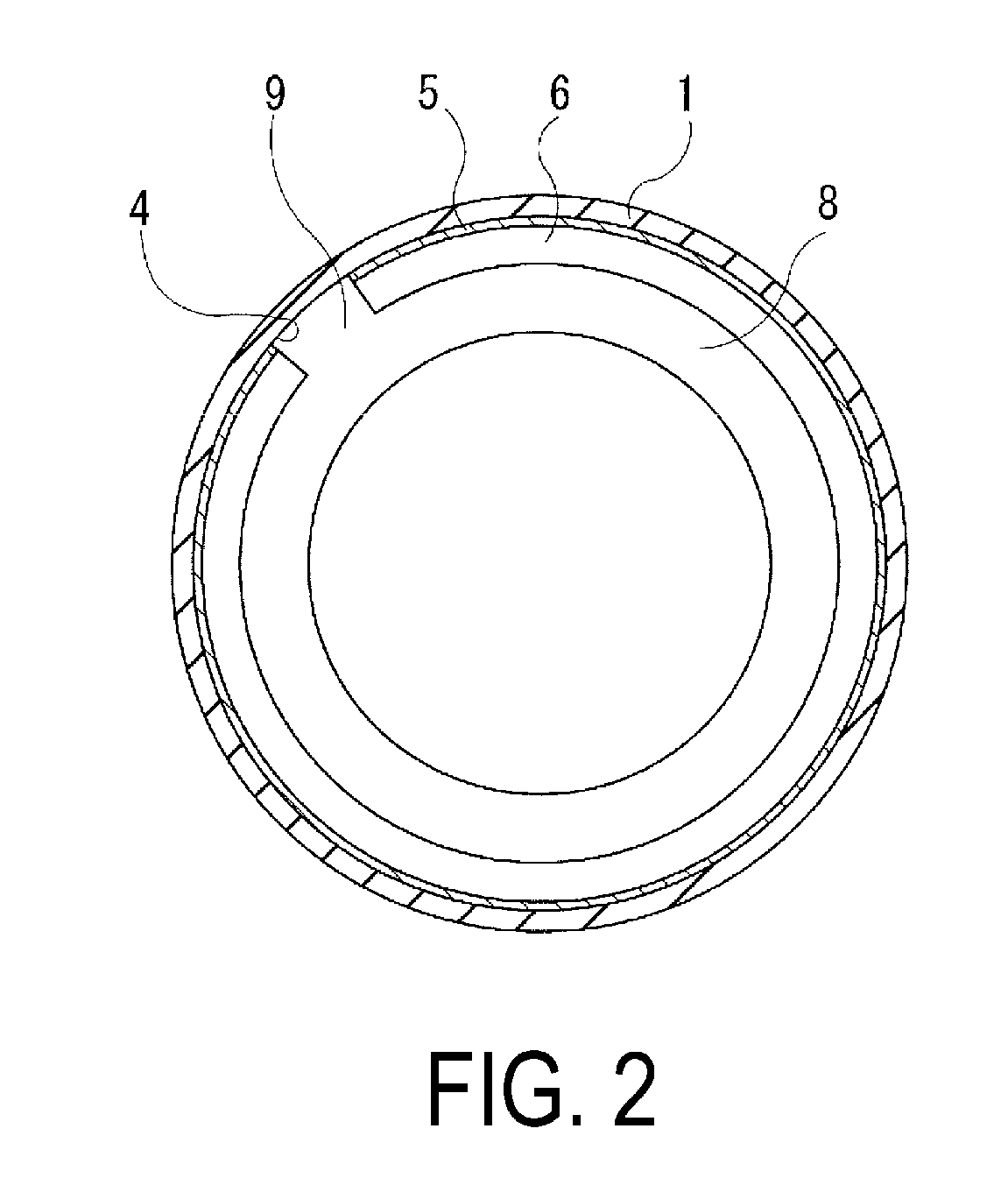
[0030]Tires of a Conventional Example and Examples 1 to 8 where the width of the cuts (width a / width A×100%) and the depth of the cuts (depth d / thickness D×100%) were set as in Table 1-1 and Table 1-2 were prepared for a pneumatic tire provided with an annular-shaped tread portion extending in a tire circumferential direction, a pair of sidewall portions disposed on both sides of the tread portion, and a pair of bead portions disposed on an inner side in a tire radial direction of the sidewall portions, at a tire size of 275 / 35ZR20, where a band-like sound absorbing member was adhered on an inner surface of the tread portion in the tire circumferential direction.

[0031]The high-speed durability, durability, and adhering properties of the band-like sound absorbing member were evaluated for the test tires by the following testing method, and the results thereof are collectively shown in Table 1-1 and Table 1-2.

[0032]High-Speed Durability:

[0033]The test tires were assembled on wheels ha...


PUM


Abstract

A pneumatic tire includes: an annular-shaped tread portion extending in a tire circumferential direction; a pair of sidewall portions disposed on both sides of the tread portion; and a pair of bead portions disposed on an inner side in a tire radial direction of the sidewall portions; wherein a band-like sound absorbing member is adhered on an inner surface of the tread portion in the tire circumferential direction; and a plurality of cuts with an angle θ with regard to the tire circumferential direction within a range of 40°≤θ≤90° are formed on both end portions in a lateral direction of the band-like sound absorbing member, and the cuts are connected only to one end portion in the lateral direction of the band-like sound absorbing member.

Description

TECHNICAL FIELD[0001]The present technology relates to a pneumatic tire, and particularly relates to a pneumatic tire that can promote heat dissipation from a band-like sound absorbing member, and improve high-speed durability, in conjunction with relieving stress occurring on the band-like sound absorbing member when cornering, and improving the durability of the band-like sound absorbing member, by providing a cut on the band-like sound absorbing member adhered to an inner surface of the tire.BACKGROUND ART[0002]Cavernous resonance caused by the vibration of the air filled in a cavity portion of a tire is one cause of tire noise. Cavernous resonance is caused by a tread portion of a tire contacting a road surface during vehicle travel vibrating due to unevenness on the road surface, and the vibration is caused by air inside a cavity portion of a tire vibrating. The cavernous resonance has a frequency range where noise is generated, and reducing the noise level of the frequency ran...

Claims


Application Information

Patent Timeline
IPC IPC(8): B60C19/00
CPCB60C19/002B60C5/00
Inventor HOSHIBA, TAKASHISHINZAWA, TATSURONARUSE, MASAHIRO
Owner YOKOHAMA RUBBER CO LTD
Why Eureka
Try Eureka