Heat exchange device and equipment system having heat exchange ability

a technology of heat exchange device and equipment system, which is applied in the direction of lighting and heating apparatus, electrical apparatus construction details, instruments, etc., can solve the problems of increasing the computation speed of chips, the temperature of heat sources is extremely high, and the contact area of heat sources is decreased, so as to achieve enhanced cooling effect, the effect of decreasing the temperature cannot be poor, and the temperature cannot be reduced

Inactive Publication Date: 2019-03-14
CASING MACRON TECH
View PDF0 Cites 3 Cited by
  • Summary
  • Abstract
  • Description
  • Claims
  • Application Information

AI Technical Summary

Benefits of technology

[0025]Regarding the heat exchange device and the equipment system using the same provided by the present disclosure, the heat sink of the heat exchange device can contact a heat source directly, such that effects of directly dissipating heat and decreasing a temperature can be performed, and a cooling effect is enhanced. Further, after the heat-transfer medium is cycled, the heat-transfer medium at the heat sink can maintain a low temperature state, and even after a long-term usage, the effect of decreasing the temperatu...

Problems solved by technology

However, as the technology advances, contacting areas of the heat sources decrease, and computation speeds of chips increase, such that temperatures of heat sources extremely increase.
If merely the fins are used for heat dissipation, heat dissipation efficiency may be poor.
Further, a case of the computer is semi-closed, being hard to dissipate the heat, and after the computer is used for a long time, dust may be accumulated in the case of the computer, which decreases the heat dissipation efficiency.
However, regarding cooling mechanism of the liquid cooling system 40, the flowing cycle is limited by an ...

Method used


Image

  • Heat exchange device and equipment system having heat exchange ability
  • Heat exchange device and equipment system having heat exchange ability
  • Heat exchange device and equipment system having heat exchange ability

Examples


Embodiment Construction

[0044]To understand the technical features, content and advantages of the present disclosure and its efficacy, the present disclosure will be described in detail with reference to the accompanying drawings. The drawings are for illustrative and auxiliary purposes only and may not necessarily be the true scale and precise configuration of the present disclosure. Therefore, the scope of the present disclosure should not be limited to the scale and configuration of the attached drawings.

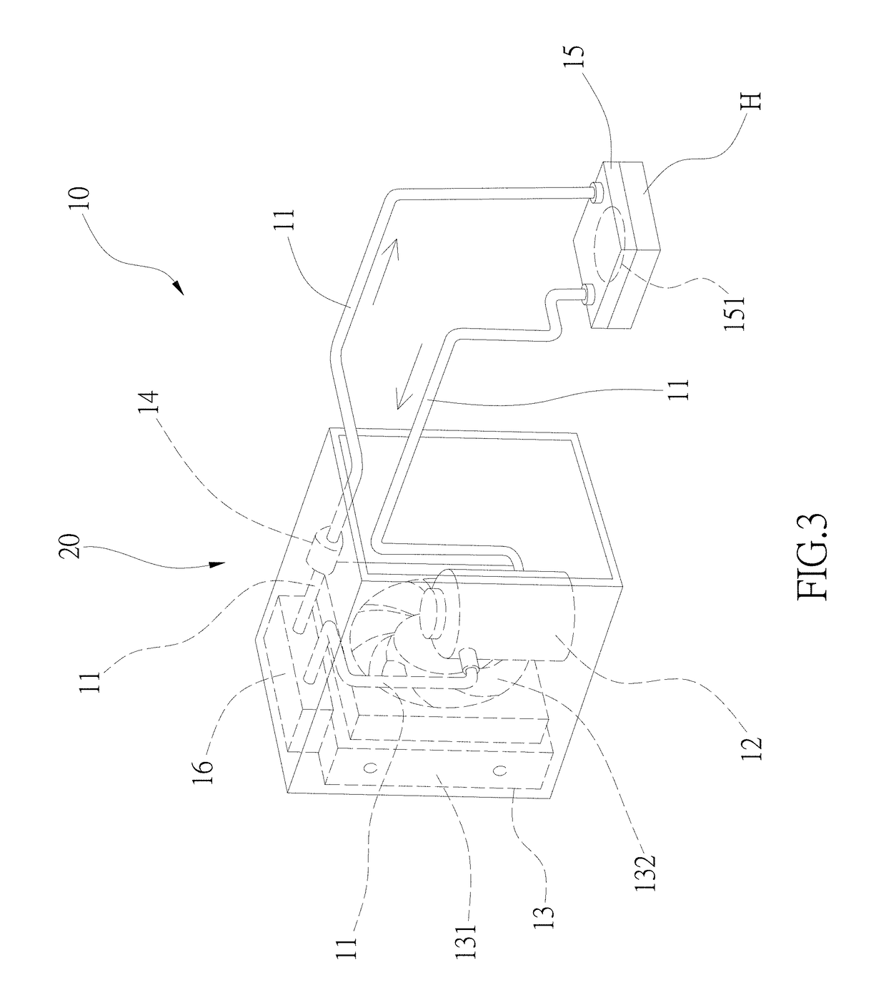
[0045]Referring to FIG. 3, which is a three-dimensional view of a heat exchange device according to a first embodiment of the present disclosure, the heat exchange device has heat exchange ability, and thus heat can be sent to a cool end from a heat end. The heat exchange device 10 comprises a pipe unit 11, a vapor / gas pressurizer 12, a heat dissipation device 13, a throttling device 14, a heat sink 15, a control unit 16 and a case 20.

[0046]The pipe unit 11 is filled with heat-transfer medium (not shown...


PUM


Abstract

A heat exchange device and an equipment system using the same are illustrated. A pipe unit is filled with a heat-transfer medium, and via cycling of a vapor/gas pressurizer, a heat dissipation device and a throttling device, the heat-transfer medium flows to a heat sink having a heat sinking surface, and the heat sinking surface contacts a heat source, such that the heat-transfer medium flowing to the heat sink passes the heat sinking surface to take away the heat of the heat source. The heat exchange device is disposed in an equipment having at least a power supply and at least a working unit, wherein the working unit forms a heat source when operating, and the working unit contacts the heat sinking surface, such that a direct heat absorption and an efficient heat cycle are performed to achieve a heat dissipation effect.

Description

BACKGROUND1. Technical Field[0001]The present disclosure relates to a heat exchange device and an equipment system having the heat exchange device, for example, a host computer with heat dissipation ability, and the application of the equipment system having the heat exchange device is not limited to the host computer.2. Description of Related Art[0002]A conventional heat dissipation system, such as the heat dissipation system installed in a computer for heat sources of a central processing unit (CPU) and other chips, usually has fins disposed on the heat sources for dissipating and conducting heat. By leading the heat out from the heat sources via the fins, a heat dissipation process can be carried out. However, as the technology advances, contacting areas of the heat sources decrease, and computation speeds of chips increase, such that temperatures of heat sources extremely increase. If merely the fins are used for heat dissipation, heat dissipation efficiency may be poor. Further...

Claims


Application Information

Patent Timeline
IPC IPC(8): G06F1/20F25B1/00H05K7/20
CPCG06F1/206F25B1/00H05K7/20145H05K7/20154H05K7/20381H05K7/20209H05K7/20172G06F1/20H05K7/20354H05K7/20327H05K7/20263G06F2200/201F25B2400/071
Inventor HSIAO, YI-CHANG
Owner CASING MACRON TECH
Why Eureka
Try Eureka