Article Storage Facility

a technology for storage facilities and articles, applied in storage devices, conveyor parts, electrical appliances, etc., can solve the problems of large movement trajectory of plurality of arms, difficult arrangement of storage racks and transfer devices close to each other, and increase separation space, reduce distance, and reduce the effect of depth

Active Publication Date: 2019-06-27
DAIFUKU CO LTD
View PDF8 Cites 3 Cited by
  • Summary
  • Abstract
  • Description
  • Claims
  • Application Information

AI Technical Summary

Benefits of technology

[0007]With the above-described configuration, a trajectory of movement of the advancing / retracting mechanism when the supporting body is moved back and forth is a trajectory that protrudes, to the first side, from a trajectory of movement of the supporting body, due to the fact that the first coupling part is located on the first side relative to the second coupling part. In this regard, with the above-described configuration, the rack body is formed such that, in the first region, which is a region in the depth direction and includes an end on the front side of the rack body, a distance from the width directional center, which is the center in the lateral width direction of the rack body, to the first supporting portion (hereinafter, referred to as a “first distance”) is longer than a distance from the width directional center to the second supporting portion (hereinafter, referred to as a “second distance”). Accordingly, in the first region, the first distance being longer than the second distance makes it possible to enlarge the separation space formed between the first supporting portion and the second supporting portion toward the first side. Since the separation space can be enlarged to the first side in the first region in this manner, it is easy to arrange the rack body and the transfer device close to each other in the depth direction while avoiding interference between the rack body and the trajectory of movement of the advancing / retracting mechanism, compared to a case where the first distance is equal to the second distance in the first region. As a result, it is possible to realize an article storage facility that uses the advancing / retracting mechanism configured to move back and forth the supporting body that supports an article, by rotating the plurality of arms rotatably coupled to each other, and in which the distance, in the depth direction, between the storage rack and the transfer device can be reduced.

Problems solved by technology

However, as in the configuration of Patent Document 1 in which an advancing / retracting mechanism of the transfer device rotates a plurality of arms rotatably coupled to each other to move back and forth a supporting body that supports the article, a trajectory of movement of the plurality of arms when the supporting body is moved back and forth is likely to be large when viewed in the vertical direction, and it is not easy to arrange the storage rack and the transfer device close to each other in the depth direction while avoiding interference between the storage rack and the transfer device.

Method used


Image

  • Article Storage Facility
  • Article Storage Facility
  • Article Storage Facility

Examples


Embodiment Construction

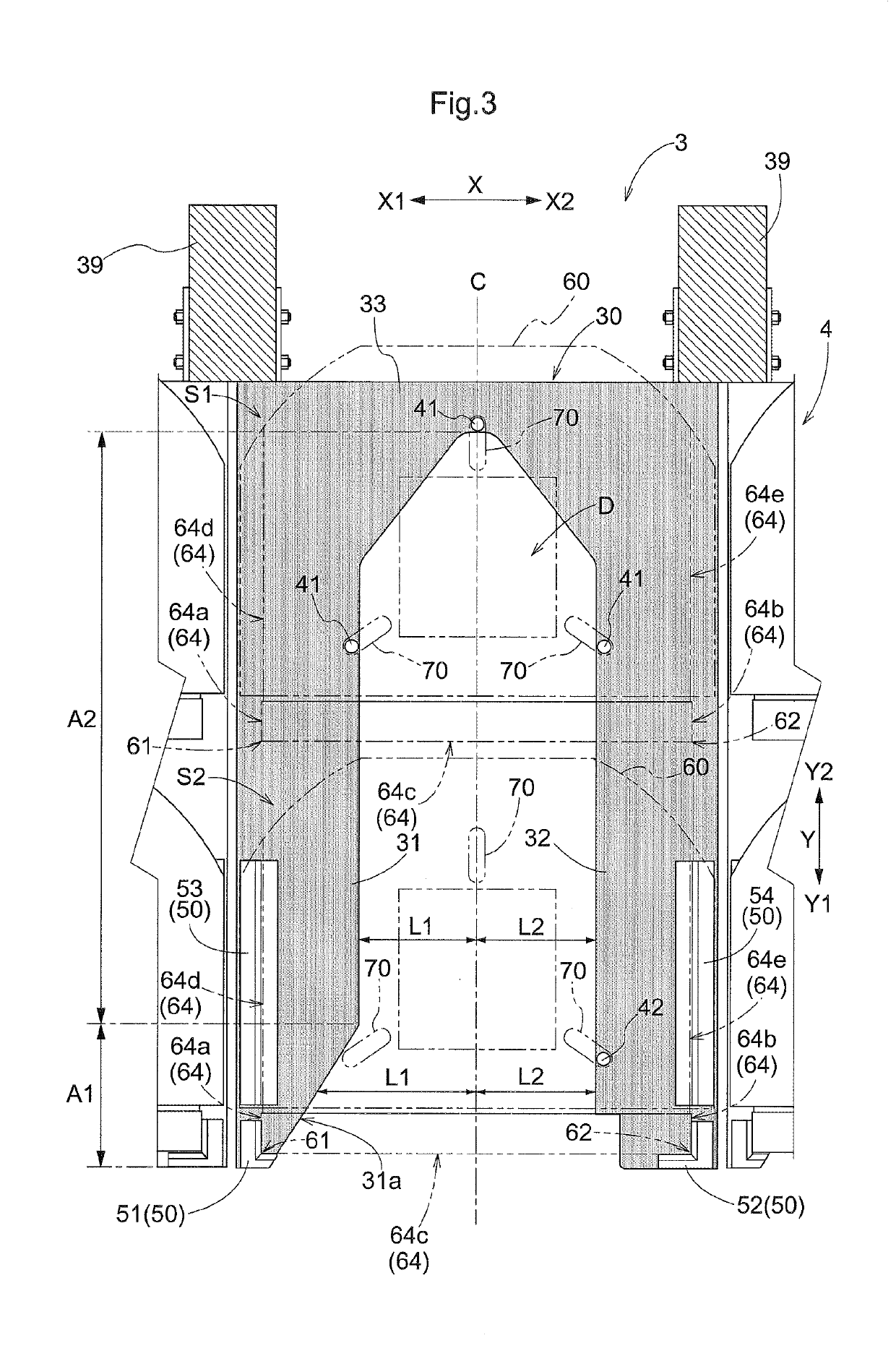
[0020]An embodiment of an article storage facility will be described with reference to the drawings. In the present embodiment, a first distance L1 corresponds to a “distance from the width directional center to a first supporting portion”, a second distance L2 corresponds to a “distance from the width directional center to a second supporting portion”, a first projected position P1 corresponds to a “specific position”, and a first storage place S1 corresponds to a “specific storage place”.

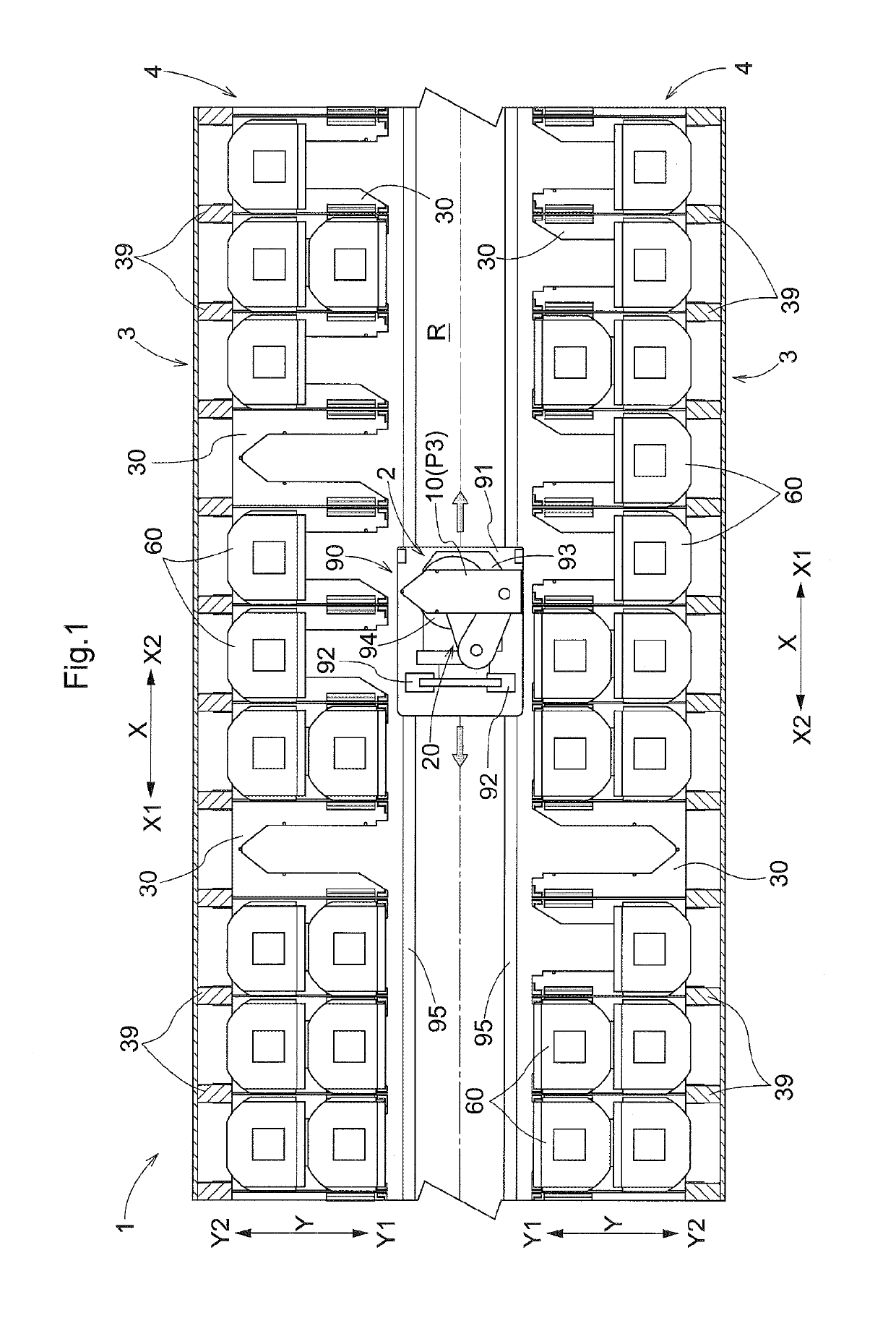
[0021]As shown in FIG. 1, an article storage facility 1 includes storage racks 3 in which articles 60 are stored, and a transfer device 2 configured to transfer the articles 60 to the storage racks 3 from front sides Y1 of the storage racks 3. The storage racks 3 are provided for articles 60 (storage objects) that each have, at a plurality of positions on the bottom 63 thereof, positioning recesses 70 (see FIG. 3) that are recessed upward. In other words, the articles 60 that have the recesses 70 ...


PUM


Abstract

An advancing/retracting mechanism includes a first arm, a second arm, a first coupling part that couples the first arm and the second arm, and a second coupling part that couples a supporting body and the first arm. A transfer device is configured to move the supporting body back and forth with the first coupling part located on a first side relative to the second coupling part, by rotating the first arm and the second arm. In a first region, which is a region in the depth direction and includes an end on the front side of the rack body, a distance from the width directional center to the first supporting portion is longer than a distance from the width directional center to the second supporting portion.

Description

CROSS-REFERENCE TO RELATED APPLICATION[0001]This application claims priority to Japanese Patent Application No. 2017-245292 filed Dec. 21, 2017, the disclosure of which is hereby incorporated in its entirety by reference.TECHNICAL FIELD[0002]The present invention relates to an article storage facility that includes a storage rack that stores articles, and a transfer device that transfers the articles to the storage rack from the front side of the storage rack.BACKGROUND OF THE INVENTION[0003]One example of an article storage facility as described above is disclosed in JP 2008-174335A (Patent Document 1). A stocker (1) disclosed in Patent Document 1 includes a storage rack (2) on which storage articles (9) are placed, and a stacker device (4) that transfers a storage article (9) to the storage rack (2) from the front side of the storage rack (2). As shown in FIG. 4 and the like of Patent Document 1, the stacker device (4) includes a hand (47) that supports the storage article (9) fro...

Claims


Application Information

Patent Timeline
Patent Type & Authority Applications(United States)
IPC IPC(8): H01L21/677B65G1/04
CPCH01L21/67769H01L21/67766B65G1/04B65G1/0407H01L21/67379H01L21/6773H01L21/67775
Inventor ABE, TAKESHIYOSHIMOTO, TADAHIRO
Owner DAIFUKU CO LTD
Why Eureka
Try Eureka