Switch apparatus

a switch and apparatus technology, applied in the direction of pulse technique, line-transmission details, instruments, etc., can solve the problems of increasing the cost and design difficulty of the switch apparatus, adding a parasitic effect to the signal transceiving end, and increasing the cost and design difficulty

Active Publication Date: 2019-07-25
RICHWAVE TECH CORP
View PDF0 Cites 0 Cited by
  • Summary
  • Abstract
  • Description
  • Claims
  • Application Information

AI Technical Summary

Benefits of technology

[0004]A switch apparatus in an embodiment of the invention includes a first signal control switch, a first switch circuit, a first blocking capacitor and a first surge current dissipation circuit (SCD-circuit). The first signal control switch is coupled between a first signal transceiving end and a second signal transceiving end, and configured to be turned on or off according to a first control signal. The first switch circuit is coupled between the first signal transceiving end and a first reference voltage end, and configured to be turned on or off according to a second control signal. The first blocking capacitor is serially coupled between the first switch circuit and the first reference voltage end. The first SCD-circuit has a first end coupled between the first switch circuit and the first blocking capacitor and a second end coupled to the first reference voltage end, and includes a first Zener diode circuit or at least one first diode circuit. The at least one first diode circuit has one or more first diodes coupled in series. The one or more first diodes coupled in series are coupled between the first end and the second end of the first SCD-circuit according to a first polarity direction.
[0005]A switch apparatus in an embodiment of the invention includes a first signal control switch, a first switch circuit, a first blocking capacitor, a first SCD-circuit, a second signal control switch, a second switch circuit and a second blocking capacitor. The first signal control switch is coupled between a first signal transceiving end and a second signal transceiving end, and configured to be turned on or off according to a first control signal. The first switch circuit is coupled between the first signal transceiving end and a first reference voltage end, and configured to be turned on or off according to a second control signal. The first blocking capacitor is serially coupled between the first switch circuit and the first reference voltage end. The first SCD-circuit has a ...

Problems solved by technology

The SCD-circuit disposed on the signal transceiving end may cause additional parasitic effect on the signal transceiving end.
Therefore, design for the switch apparatus also becomes eve...

Method used


Image

  • Switch apparatus
  • Switch apparatus
  • Switch apparatus

Examples


Embodiment Construction

[0016]Reference will now be made in detail to the present preferred embodiments of the invention, examples of which are illustrated in the accompanying drawings. Wherever possible, the same reference numbers are used in the drawings and the description to refer to the same or like parts.

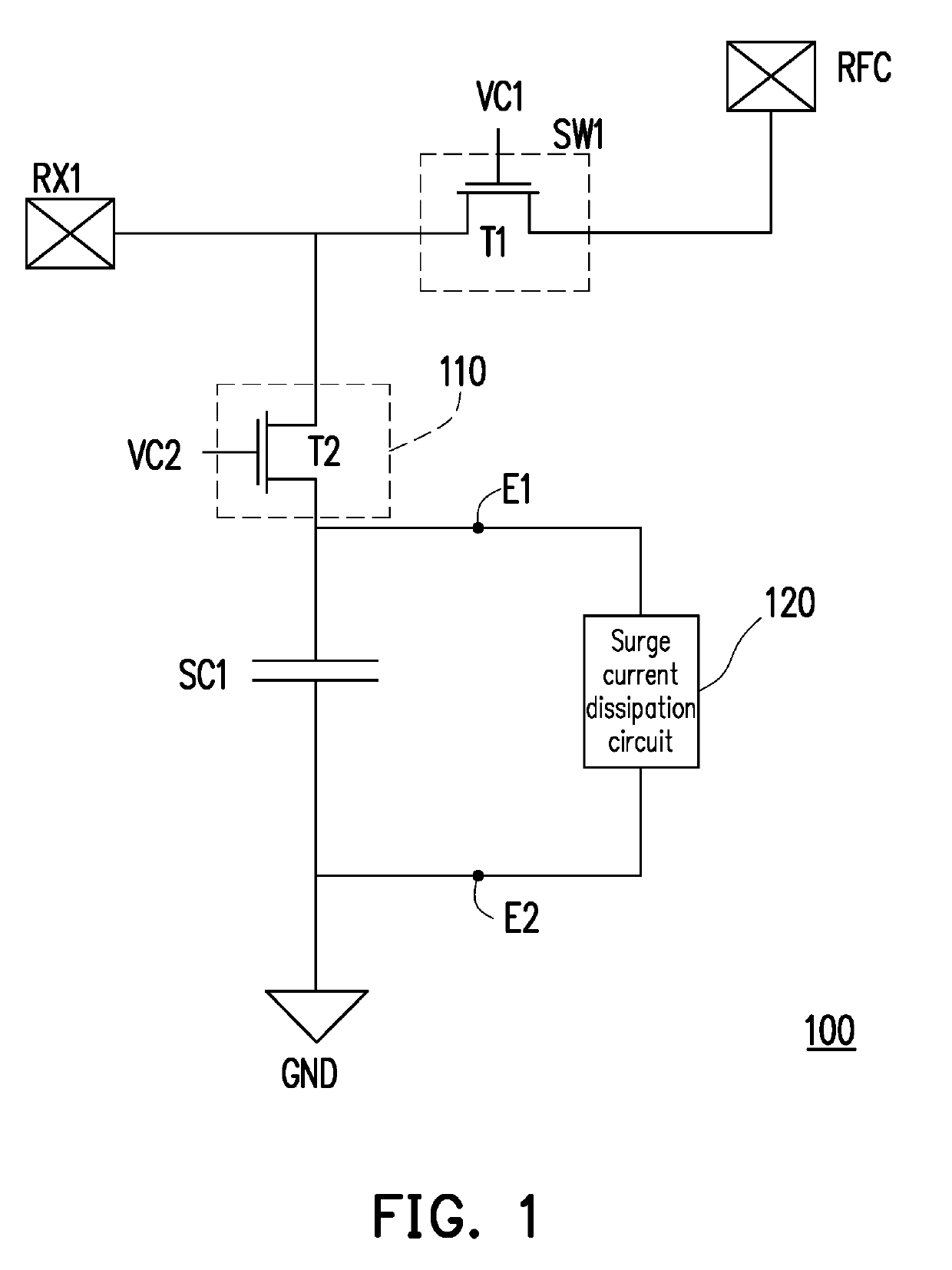
[0017]Embodiments of the disclosure provide a plurality of switch apparatuses, which are capable of conducting a dissipating operation for a surge current when a surge occurs. With reference to FIG. 1, FIG. 1 is a schematic diagram illustrating a switch apparatus in an embodiment of the invention. A switch apparatus 100 may be used to transceive high frequency signals such as radio-frequency (RF) signals. The switch apparatus 100 includes a switch SW1, a switch circuit 110, a capacitor SC1 and a surge current dissipation circuit (SCD-circuit) 120. The switch SW1 includes a transistor T1, and is coupled between an end RX1 and an end RFC. The switch SW1 receives a control signal VC1 to be turned on or ...


PUM


Abstract

A switch apparatus is provided. The switch apparatus includes a signal control switch, a switch circuit, a blocking capacitor and a surge current dissipation circuit. The signal control switch and the switch circuit are respectively controlled by a first control signal and a second control signal to be turned on or off. The blocking capacitor is serially coupled between the switch circuit and a reference voltage end. The surge current dissipation circuit includes a Zener diode circuit or at least one diode circuit, and the at least one diode circuit has one or more diodes coupled in series. The one or more diodes coupled in series are coupled between two ends of the surge current dissipation circuit according to a first polarity direction.

Description

CROSS-REFERENCE TO RELATED APPLICATION[0001]This application claims the priority benefit of Taiwan application serial no. 107101971, filed on Jan. 19, 2018. The entirety of the above-mentioned patent application is hereby incorporated by reference herein and made a part of this specification.BACKGROUND OF THE INVENTION1. Field of the Invention[0002]The invention relates to a switch apparatus, and more particularly, to a switch apparatus capable of dissipating a surge current.2. Description of Related Art[0003]In the conventional technical field, protection for a surge (e.g., Electrostatic Discharge (ESD) or Electrical Overstress (EOS)) occurred in a switch apparatus is often carried out by disposing a surge current dissipation circuit (SCD-circuit) on a signal transceiving end. The SCD-circuit disposed on the signal transceiving end may cause additional parasitic effect on the signal transceiving end. Consequently, quality of transceiving signals on the signal transceiving end is th...

Claims


Application Information

Patent Timeline
IPC IPC(8): H02H9/04H03K17/693G05F3/18H02H9/02
CPCH02H9/046H03K17/693G05F3/185H02H9/025H04B3/46H03K17/081
Inventor CHAO, CHUAN-CHEN
Owner RICHWAVE TECH CORP
Why Eureka
Try Eureka