Reflective optical stack for privacy display

a technology of optical stacks and privacy displays, applied in the field of illumination, can solve the problems of limited display to privacy only function, and achieve the effects of reducing the thickness between the slm and the viewer, increasing image fidelity, and increasing diffusion

Active Publication Date: 2020-01-23
REALD SPARK LLC
View PDF11 Cites 37 Cited by
  • Summary
  • Abstract
  • Description
  • Claims
  • Application Information

AI Technical Summary

Benefits of technology

[0008]Advantageously a directional display may be provided which provides high reflectivity and low luminance for off-axis viewing positions; and low reflectivity and high luminance for on-axis viewing positions. Such increased reflectivity and reduced luminance provides enhanced privacy performance including increased visual security level (VSL) for off-axis viewers of the display in an ambiently illuminated environment. A privacy display may be provided with low visibility of images for an off-axis snooper viewing the display in ambient conditions. The on-axis viewer may observe a substantially unmodified display. A low stray light display may be provided with low image visibility for some viewers and high image visibility for other viewers. The display may be used in an automotive vehicle to prevent visibility to passengers or drivers.
[0062]Advantageously a switchable privacy display may be provided with high image visibility over a wide field of view in a public mode of operation. A wide angle backlight may be provided, with reduced cost and higher ruggedness in comparison to collimated backlights. In a privacy mode of operation, high VSLs may be achieved over a wide field of view in which an off-axis snooper may be positioned, with low display reflectivity. Some of the retarders and additional polarisers may be arranged between the backlight and the SLM so that diffusers with surface roughness may be arranged on the front surface of the display to minimise the visibility of frontal reflections while achieving high pixel fidelity and high image contrast. Chromaticity and luminance roll-offs may be symmetric. Scatter from the SLM may not impact the light that transmits through one of the retarders and the additional polariser so that VSL may be increased.

Problems solved by technology

A privacy function may be provided by micro-louvre optical films that transmit a high luminance from a display in an on-axis direction with low luminance in off-axis positions, however such films are not switchable, and thus the display is limited to privacy only function.

Method used


Image

  • Reflective optical stack for privacy display
  • Reflective optical stack for privacy display
  • Reflective optical stack for privacy display

Examples


Embodiment Construction

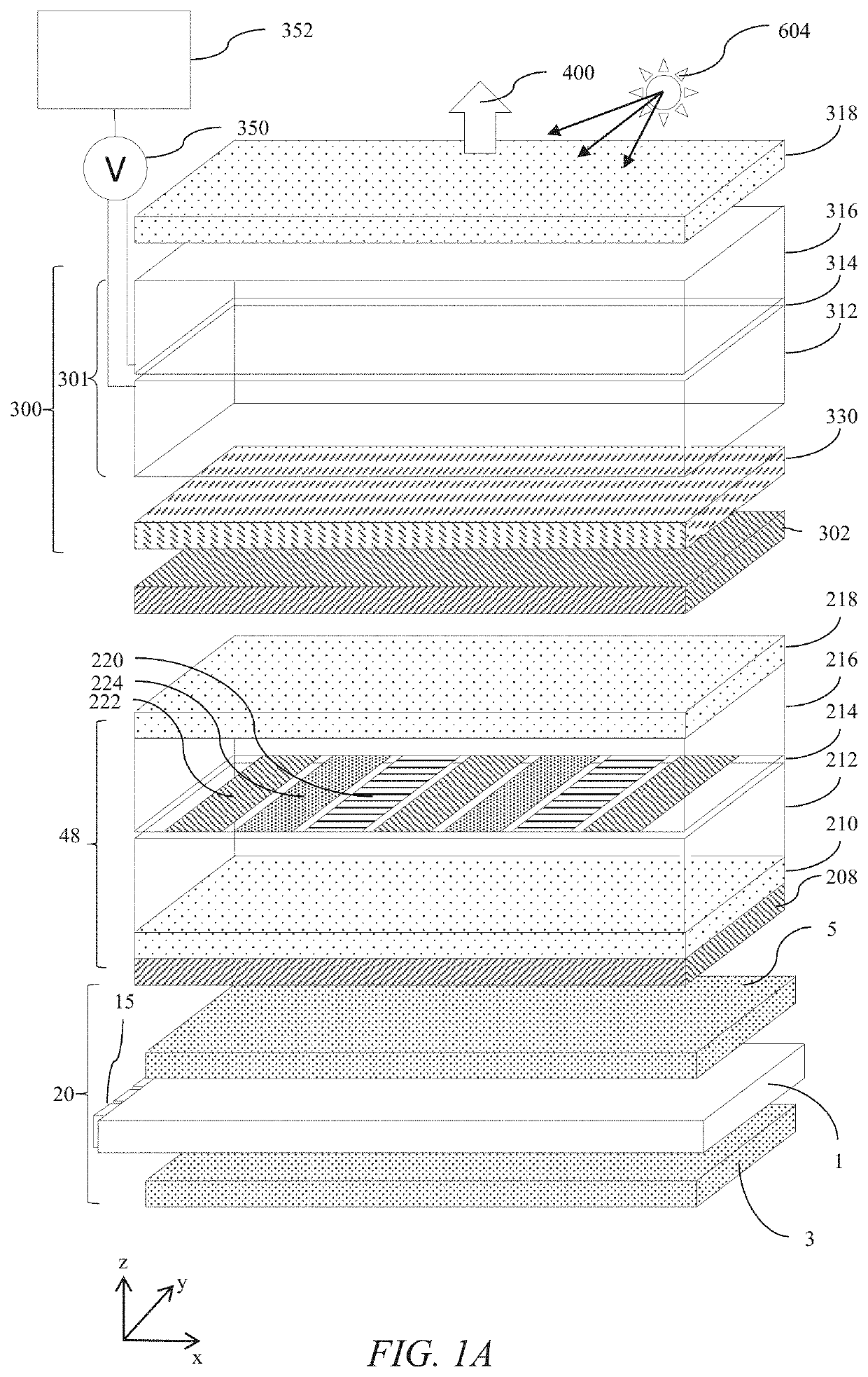
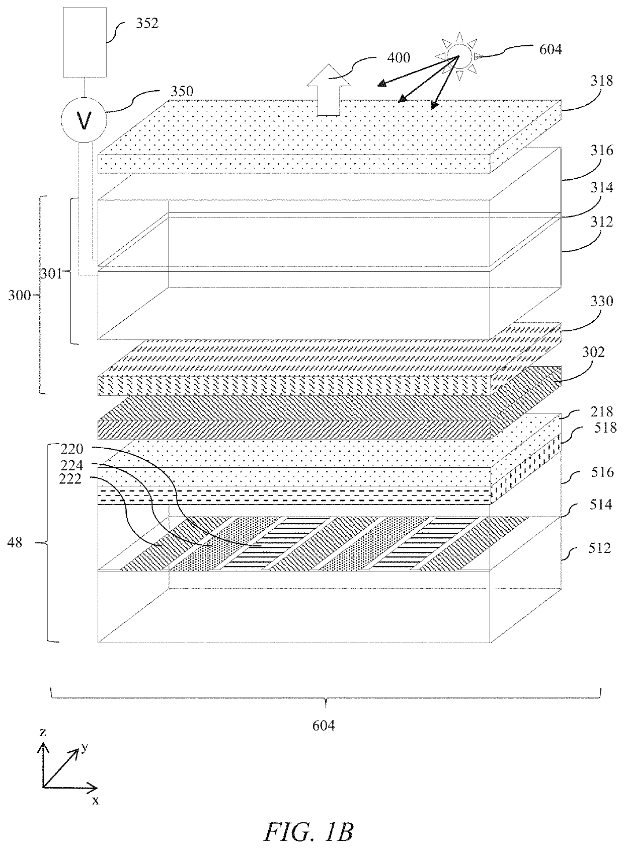
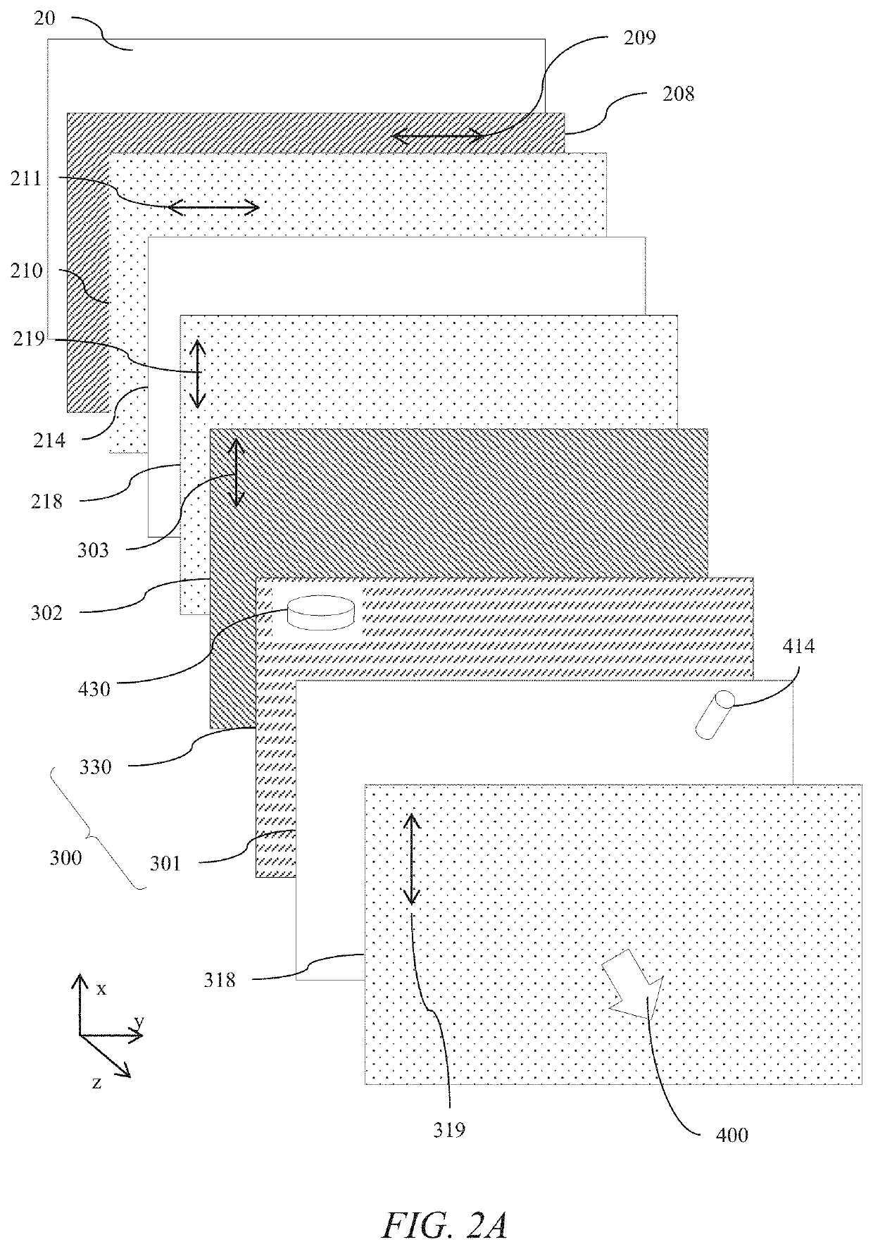
[0202]Terms related to optical retarders for the purposes of the present disclosure will now be described.

[0203]In a layer comprising a uniaxial birefringent material there is a direction governing the optical anisotropy whereas all directions perpendicular to it (or at a given angle to it) have equivalent birefringence.

[0204]The optical axis of an optical retarder refers to the direction of propagation of a light ray in the uniaxial birefringent material in which no birefringence is experienced. This is different from the optical axis of an optical system which may for example be parallel to a line of symmetry or normal to a display surface along which a principal ray propagates.

[0205]For light propagating in a direction orthogonal to the optical axis, the optical axis is the slow axis when linearly polarized light with an electric vector direction parallel to the slow axis travels at the slowest speed. The slow axis direction is the direction with the highest refractive index at t...


PUM

PropertyMeasurementUnit
wavelengthaaaaaaaaaa

Abstract

A privacy display comprises a polarised output spatial light modulator, reflective polariser, plural polar control retarders and a polariser. In a privacy mode of operation, on-axis light from the spatial light modulator is directed without loss, whereas off-axis light has reduced luminance. Further, display reflectivity is reduced for on-axis reflections of ambient light, while reflectivity is increased for off-axis light. The visibility of the display to off-axis snoopers is reduced by means of luminance reduction and increased frontal reflectivity to ambient light. In a public mode of operation, the liquid crystal retardance is adjusted so that off-axis luminance and reflectivity are unmodified.

Description

TECHNICAL FIELD[0001]This disclosure generally relates to illumination from light modulation devices, and more specifically relates to reflective optical stacks for use in a display including a privacy display.BACKGROUND[0002]Privacy displays provide image visibility to a primary user that is typically in an on-axis position and reduced visibility of image content to a snooper, that is typically in an off-axis position. A privacy function may be provided by micro-louvre optical films that transmit a high luminance from a display in an on-axis direction with low luminance in off-axis positions, however such films are not switchable, and thus the display is limited to privacy only function.[0003]Switchable privacy displays may be provided by control of the off-axis optical output.[0004]Control may be provided by means of luminance reduction, for example by means of switchable backlights for a liquid crystal display (LCD) spatial light modulator (SLM). Display backlights in general emp...

Claims


Application Information

Patent Timeline
Patent Type & Authority Applications(United States)
IPC IPC(8): G02F1/1335G02B5/30G02F1/1343G02F1/1337G02B30/25
CPCG02F1/133528G02F2001/133531G02F1/1337G02F2203/12G02F1/133536G02F1/1323G02B5/3025G02B27/288G02F2203/62G02F1/13363G02F2413/10B60J3/04G02F1/13712G02F1/133634G02F1/133773G02F1/133742G02F1/133738G02F1/133531
Inventor ROBINSON, MICHAEL G.WOODGATE, GRAHAM J.HARROLD, JONATHANRAMSEY, ROBERT A.
Owner REALD SPARK LLC
Why Eureka
Try Eureka