
Method For Variable Displacement Engine
- Summary
- Abstract
- Description
- Claims
- Application Information
AI Technical Summary
Benefits of technology
Problems solved by technology
Method used
Image

Examples
Embodiment Construction
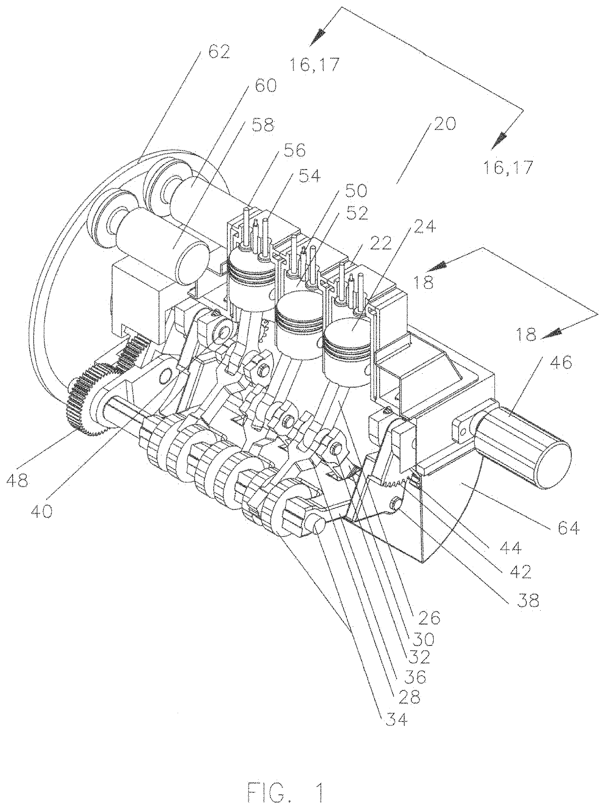
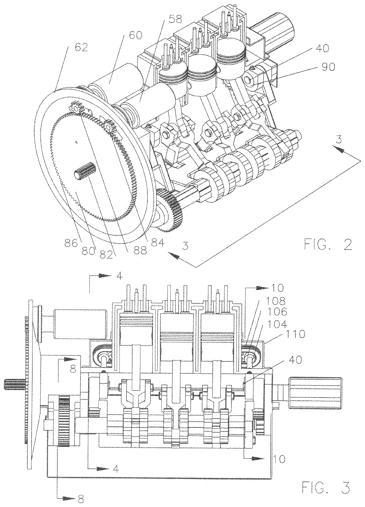
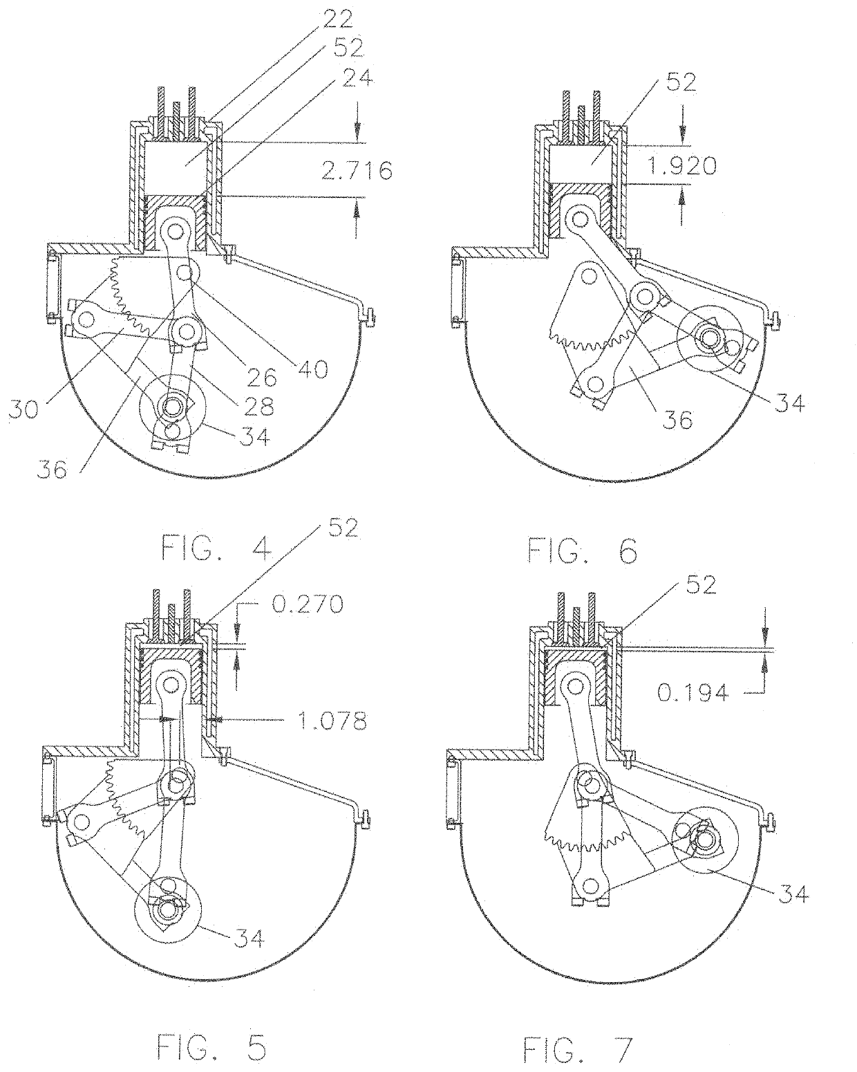
[0035]Referring now to FIG. 1, a perspective cutaway of an internal combustion engine 20 is shown with engine block 22 housing piston 24 which is connected to piston connecting rod 26. Piston connecting rod 26 is connected to crankshaft connecting rod 28 and idler connecting rod 30 by floating pin 32. Crankshaft connecting rod 28 is also connected to crankshaft 34 which is mounted in swivel 36. Idler connecting rod 30 is also connected to swivel 36 at idler arm pivot axle 38. Swivel 36 rotates about pivot pin 40 and is driven by gear 42. Gear 42 is driven by gear 44 which is in turn driven by rotator 46, as will be discussed later. Crankshaft 34 drives gear 48 which delivers the engine power to the drive shaft which will be discussed later.
[0036]Fuel injector 50 is shown in a position to inject fuel into combustion chamber 52. Intake valve 54 and exhaust valve 56 are illustrated. Valve operating cams and exhaust manifolds are not illustrated as they are well known in the art. Starte...
PUM
 Abstract
Description
Claims
Application Information