System for mounting an annular component on a shaft

a technology of annular components and shafts, applied in the direction of positive displacement liquid engines, program control, instruments, etc., can solve the problems of exacerbated inaccuracy of operators, and achieve the effects of less reliance on operators, faster mounting, and more accurate mounting

Active Publication Date: 2020-07-30
AB SKF
View PDF0 Cites 0 Cited by
  • Summary
  • Abstract
  • Description
  • Claims
  • Application Information

AI Technical Summary

Benefits of technology

[0006]According to the invention, a system is provided by which the annular component may be mounted more accurately, faster, and with less reliance upon the operator.

Problems solved by technology

The Applicant has discovered that the operator's inaccuracy is exacerbated by the inaccuracy of the typical gauges used to measure the pressure and displacement, and also by the inaccuracy of the manual actuation of the hand pump typically used to provide the desired pressure.

Method used


Image

  • System for mounting an annular component on a shaft
  • System for mounting an annular component on a shaft
  • System for mounting an annular component on a shaft

Examples


Embodiment Construction

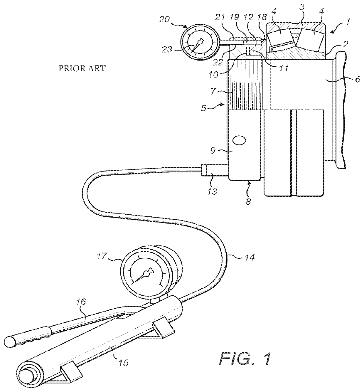
[0013]FIG. 1 shows a spherical roller bearing 1, comprising an inner race 2, which has a conically shaped bore, an outer race 3 with a spherical raceway, as well as two rows of rollers 4. The spherical roller bearing 1 is being mounted on stub 5, comprising a conically shaped part 6, as well as a screw threaded part 7. A hydraulic nut 8 has been screwed onto the screw threaded part 7. This hydraulic nut 8 comprises a nut body 9 and which has a coaxial annular chamber 10. In the chamber 10 a ring-like piston 11 has been slidingly accommodated. By means of seals 12, the piston 11 has been sealed with respect to the cylindrical walls of chamber 10. By means of connector 13, chamber 10 is connected to a hydraulic hose 14, which in turn is connected to a hydraulic hand pump 15. The oil can be pumped from pump 15 by moving handle 16 up and down. Gauge 17 shows the oil pressure. As shown in FIG. 1, piston 11 rests against inner race 2 of spherical roller bearing 1. By pumping oil into cham...


PUM


Abstract

A system for mounting an annular component on a shaft, comprising (a) a hydraulic nut having an annular coaxial cavity and a ring-like piston, displaceable within the cavity; (b) a displacement sensor for providing a displacement signal indicating the axial displacement of the piston within the cavity; (c) a wireless displacement transmitter for transmitting the displacement signal; (d) a pressure sensor for providing a pressure signal indicating a pressure within the cavity; (e) a wireless pressure transmitter for transmitting the pressure signal; (f) a pump arranged to pump fluid into the cavity; and (g) a remote control device having a communications device arranged to receive transmitted pressure and displacement signals, wherein the remote control device is arranged to output control information for controlling the pump.

Description

CROSS REFERENCE TO RELATED APPLICATIONS[0001]This application is a Continuation of (U.S.) patent application Ser. No. 15 / 005,243, filed Jan. 25, 2016, which claims the benefit of Great Britain (GB) Patent Application Number 1501456.6, filed on 29 Jan. 2015, and Great Britain (GB) Patent Application Number 1501459.0, also filed on 29 Jan. 2015, all of which are incorporated herein by reference in their entireties.TECHNICAL FIELD OF THE INVENTION[0002]The invention is related to the subject of mounting annular components, for example bearings, on a shaft. In particular, the invention can be used for mounting components having a conical bore on a complementarily-shaped shaft section.BACKGROUND OF THE INVENTION[0003]An example of this field is the mounting of a bearing on a frusta-conical seating. In the process of mounting such objects, internal stresses are generated whereby an interference fit is obtained. The conical object is stretched, whereas the shaft is compressed. The objects ...

Claims


Application Information

Patent Timeline
Patent Type & Authority Applications(United States)
IPC IPC(8): F16C35/063F04B49/06F16C19/38F16C23/08G05B19/46
CPCF04B2205/05F16C19/38F16C35/063G05B19/46G05B2219/41307F04B49/065F16C23/086F16C35/078F16C2226/12B25B27/064
Inventor DAVID, SEBASTIENELY, MARK
Owner AB SKF
Why Eureka
Try Eureka