Display driver and display device

a display driver and display device technology, applied in the field of display driver and display device, can solve the problems of image degradation, increased possibility that the display driver does not normally operate, display driver heat generation, etc., and achieve the effect of increasing the amplitude of the driving voltage, and increasing the response speed of the display driver

Pending Publication Date: 2022-01-27
LAPIS SEMICON CO LTD
View PDF5 Cites 0 Cited by
  • Summary
  • Abstract
  • Description
  • Claims
  • Application Information

AI Technical Summary

Benefits of technology

[0012]In the present invention, the display driver generates the driving voltages based on the video signal and applies the driving voltages to the source lines of the display panel. To the display driver, its internal temperature is detected, and when the temperature becomes higher than a predetermined temperature threshold, the overdrive processing to increase the amplitude of the driving voltage is stopped. Accordingly, the overdrive processing to increase the response speed of the display driver can be executed while reducing the temperature of the display driver to the predetermined temperature threshold or less.
[0013]According to the present invention, the response speed of the display driver can be increased while suppressing the image degradation due to the heat generation of the display driver.

Problems solved by technology

However, as the overdrive amount is increased, an electric power consumed by the display driver increases, thus causing heat generation of the display driver.
When the display driver continues to operate in the high temperature state, there is an increased possibility that the display driver does not normally operate, and a problem arises in that an image degradation occurs.

Method used


Image

  • Display driver and display device
  • Display driver and display device
  • Display driver and display device

Examples


embodiment 1

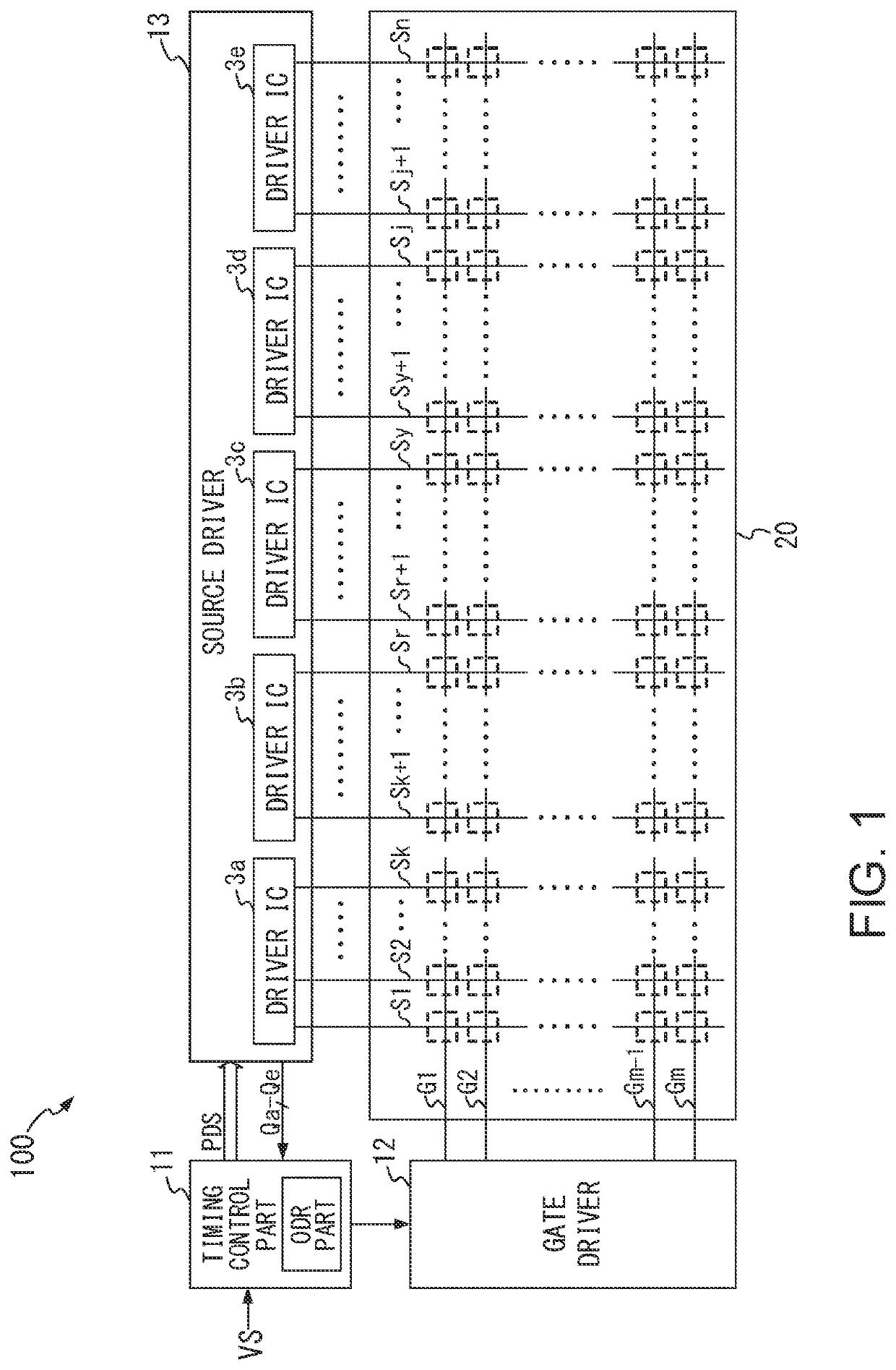
[0020]FIG. 1 is a drawing illustrating an exemplary schematic configuration of a display device 100 as an exemplary display device that includes a display driver according to the present invention. As illustrated in FIG. 1, the display device 100 includes a timing control part 11, a gate driver 12, a source driver 13, and a display panel 20.

[0021]The display panel 20 includes a capacitive image display panel, such as a liquid crystal or organic EL panel. The display panel 20 includes m (m is an integer of 2 or more) gate lines G1 to Gm each extending in a horizontal direction of a two-dimensional screen and n (n is an integer of 2 or more) source lines S1 to Sn each extending in a vertical direction of the two-dimensional screen. Display cells that serve as pixels are formed at respective intersecting portions of the gate lines and the source lines.

[0022]The timing control part 11 receives a video signal VS, extracts a horizontal synchronization signal from the video signal VS, and ...

embodiment 2

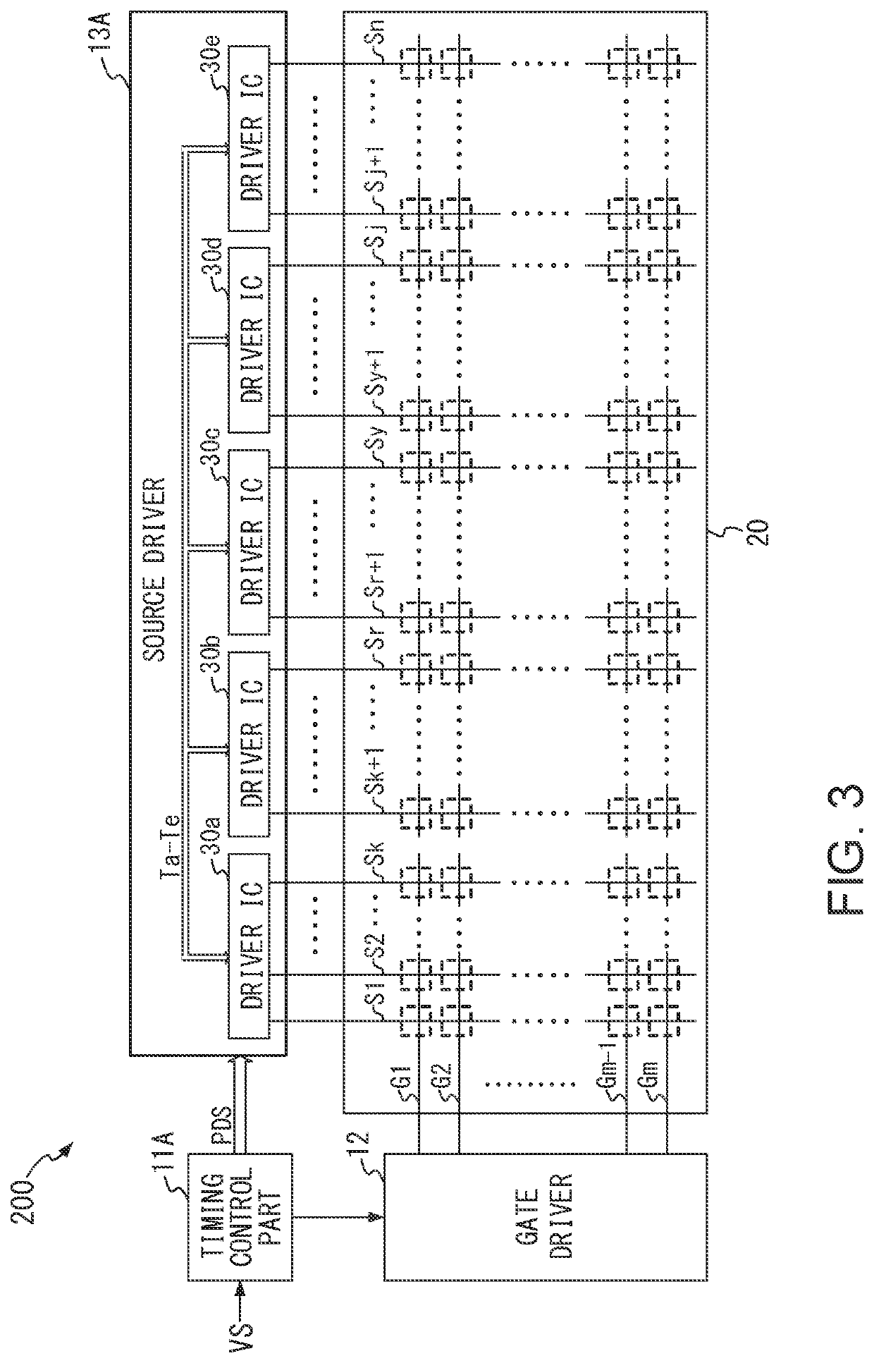
[0057]FIG. 3 is a drawing illustrating an exemplary schematic configuration of a display device 200 as another example of the display device that includes the display driver according to the present invention. In the display device 200 illustrated in FIG. 3, the configuration is the same as that of the display device 100 illustrated in FIG. 1 except that a timing control part 11A is employed instead of the timing control part 11 and a source driver 13A is employed instead of the source driver 13.

[0058]The following describes configurations mainly for the timing control part 11A and driver ICs 30a to 30e.

[0059]The timing control part 11A is one in which the function of performing the overdrive processing as described above is omitted from the timing control part 11.

[0060]That is, the timing control part 11A receives a video signal VS, extracts a horizontal synchronization signal from the video signal VS, and supplies the horizontal synchronization signal to the gate driver 12.

[0061]...


PUM


Abstract

A display driver according to the present invention generates a plurality of driving voltages based on a video signal and applies the respective driving voltages to a plurality of source lines of a display panel. The display driver includes an overdrive part and an overdrive control circuit. The overdrive part executes an overdrive processing to increase amplitudes of the driving voltages. The overdrive control circuit detects an internal temperature of the display driver and stops the overdrive processing by the overdrive part when the temperature is higher than a predetermined temperature threshold.

Description

BACKGROUND1. Technical Field[0001]The present invention relates to a display driver that generates a drive signal for driving a display panel on the basis of a video signal, and a display device that includes the display driver.2. Related Art[0002]A liquid crystal display device as a display device includes a liquid crystal display panel and a display driver that drives the liquid crystal display panel. The display driver generates a drive signal having a voltage value corresponding to a luminance indicated by a video signal and supplies the drive signal to the liquid crystal display panel. In the liquid crystal display panel, when the drive signal is received, voltage values of the drive signal are written to respective pixels, and lights are emitted from the pixels at the luminance levels corresponding to the written voltage values.[0003]Recently, because of a reduced horizontal scanning period in accordance with a larger screen and higher definition of the liquid crystal display ...

Claims


Application Information

Patent Timeline
Patent Type & Authority Applications(United States)
IPC IPC(8): G09G3/36
CPCG09G3/3696G09G2320/0233G09G2320/0252G09G2310/08G09G2320/041G09G3/3225G09G3/3648G09G2310/027G09G2340/16G09G3/3685G09G2360/16
Inventor SHIGETA, KENICHI
Owner LAPIS SEMICON CO LTD
Why Eureka
Try Eureka