Luminaire driver and method of installation

a technology of driver and light source, applied in the direction of light source, lighting device details, lighting and heating apparatus, etc., can solve the problems of generating more heat which may not be able to properly dissipate within the wiring box, the led driver becomes too large to fit into the wiring box, and the conventional retrofit led tube cannot be used, so as to achieve the effect of more wiring space and higher power

Active Publication Date: 2022-06-23
SIGNIFY HLDG BV
View PDF1 Cites 0 Cited by
  • Summary
  • Abstract
  • Description
  • Claims
  • Application Information

AI Technical Summary

Benefits of technology

[0008]One aspect of the present invention is related to an improved method using an LED driver that is capable of being inserted into and through a knockout hole of a wiring junction box. The LED driver can be locked into position, using tabs, in its final position, inside a plenum space of the building. The wiring for the LED driver...

Problems solved by technology

However, such conventional retrofit LED tubes cannot be used if the entire fluorescent lighting luminaire (i.e., removing the housing) is to be replaced with a new luminaire, e.g., a smaller, more modern fixture.
However, there are two main problems or shortcoming with such conventional LED luminaires and the conventional...

Method used


Image

  • Luminaire driver and method of installation
  • Luminaire driver and method of installation

Examples


Embodiment Construction

[0016]While this invention is susceptible of embodiment in many different forms, there are shown in the drawings and will herein be described in detail one or more specific embodiments, with the understanding that the present disclosure is to be considered as exemplary of the principles of the invention and not intended to limit the invention to the specific embodiments shown and described.

[0017]In the following, for the sake of understanding, elements of embodiments are described in operation. However, it will be apparent that the respective elements are arranged to perform the functions being described as performed by them.

[0018]Further, the invention is not limited to the embodiments, and the invention lies in each and every novel feature or combination of features described herein or recited in mutually different dependent claims.

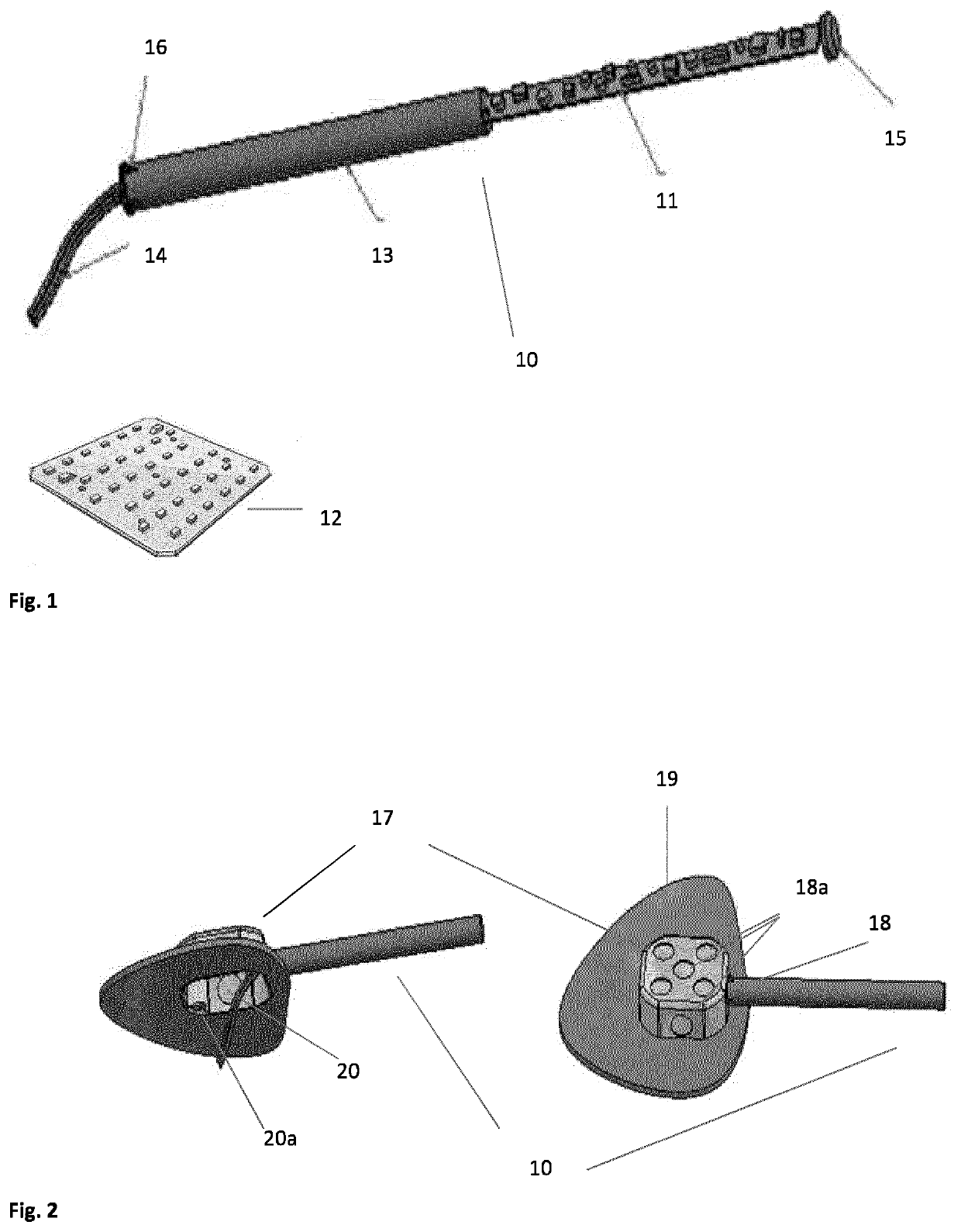
[0019]FIG. 1 shows an LED driver 10 in accordance with one embodiment of the present invention. The LED driver 10 includes a plurality of components 11...


PUM


Abstract

Drivers (10) for a luminaire (12) are disclosed. The driver (10) includes a housing (13) designed to be capable of being inserted at least partially through an opening (18) formed by removing a knockout tab (18a) in a junction box (17) and into a plenum space that is not part of the splice compartment of the junction box. A plurality of components (11) for driving the luminaire (12) are locatable within the housing (13). An electrical connection (14) is provided to electrically coupling the plurality of components (11) to the luminaire (12). A method of installation for the drivers (10) is also disclosed.

Description

FIELD OF THE INVENTION[0001]The invention relates to luminaire drivers and methods of installing the luminaire drivers, more particularly, to an LED driver having a housing capable of being inserted into and through an opening in a standard wiring junction box that can be used for either retrofit or new installations.BACKGROUND[0002]Upgrading from a traditional lighting system to newer lighting systems provides for energy savings as well as possible maintenance savings. Such traditional lighting systems include incandescent tungsten filament lamps which were the first source of light that was created. HID or metal halide lamps and fluorescent lamps that were later used to provide increased lamp life and brighter outputs over the incandescent lamps. More recently, advances in LED brightness and efficacy have allowed LED lamps and LED modules to be developed that could offer even longer lamp life and brighter outputs when properly configured, to compete with incandescent, HID or fluor...

Claims


Application Information

Patent Timeline
IPC IPC(8): F21V23/00F21V17/00F21V29/508
CPCF21V23/008F21Y2115/10F21V29/508F21V17/00H05B45/30
Inventor WIGGINTON, JACOBBUSE, JOHN
Owner SIGNIFY HLDG BV
Why Eureka
Try Eureka