CDMA cellular radio transmission system

a cellular radio and transmission system technology, applied in power management, multiplex communication, wireless communication, etc., can solve the problems of lowering the quality of communication channels, and the inability to use phase information of pilot channels for coherent detection of communication channels

Inactive Publication Date: 2000-02-22
PANASONIC INTELLECTUAL PROPERTY CORP OF AMERICA
View PDF10 Cites 65 Cited by
  • Summary
  • Abstract
  • Description
  • Claims
  • Application Information

AI Technical Summary

Problems solved by technology

If, however, W (1) is increased, the reliability of the reference signal for coherent detection is increased on one hand but since interference with communication channels (of any other station) is also increased, there arises a problem resulting in lowering communication channel quality.
Moreover, when the base station control

Method used


Image

  • CDMA cellular radio transmission system
  • CDMA cellular radio transmission system
  • CDMA cellular radio transmission system

Examples


embodiment 1

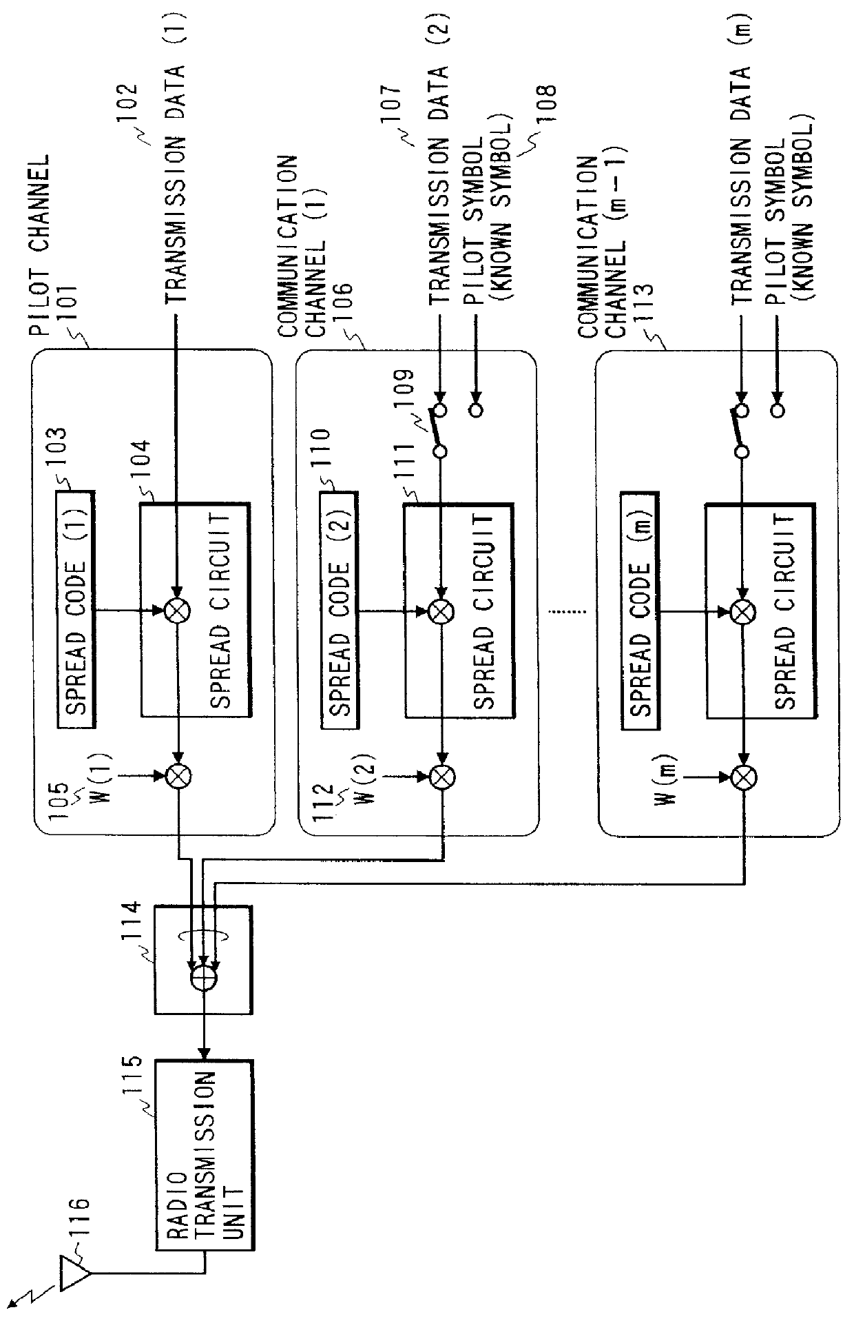
of the invention, the pilot symbol (known symbol) for the purpose of insert-type coherent detection is periodically inserted in each communication channel. Accordingly, the interference with the communication channel of any other station can be reduced, because it is unnecessary to transmit a reference signal for coherent detection with high power in comparison with the communication channel in order to attain high reliability. Even when the communication channel is transmitted by exerting transmission antenna control, radio transmission excellent in static characteristics can be carried out since the pilot symbol inserted in the communication channel is usable for coherent detection on the mobile station side.

embodiment 2

The structure of a base station in the cellular radio transmission system using the CDMA method according to Embodiment 2 of the present invention is similar to the base station according to Embodiment 1 thereof. In FIG. 1, weight W (2) to W (m) in the communication channel are used for transmission power control, that is, for giving weight to the transmission power among the communication channels. According to this embodiment, on the other hand, the value of the weight W (1) 105 of the pilot channel is set lower than the values of weight of any other communication channel, for example, transmission with W1

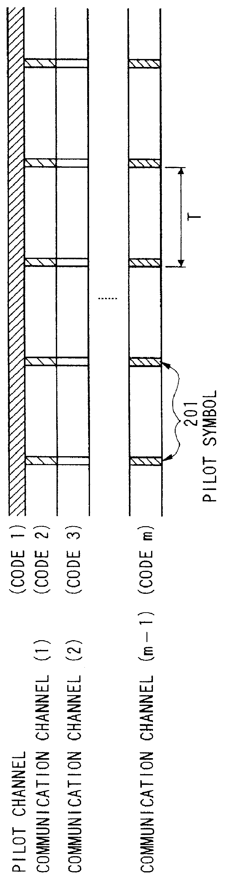
FIG. 2 is a channel format according to this embodiment of the invention. A pilot symbol 201 in addition to transmission data is inserted in each communication channel. In FIG. 2, the height of each channel indicates the transmission power thereof. Although the weight W (2) to W (m) o...

embodiment 3

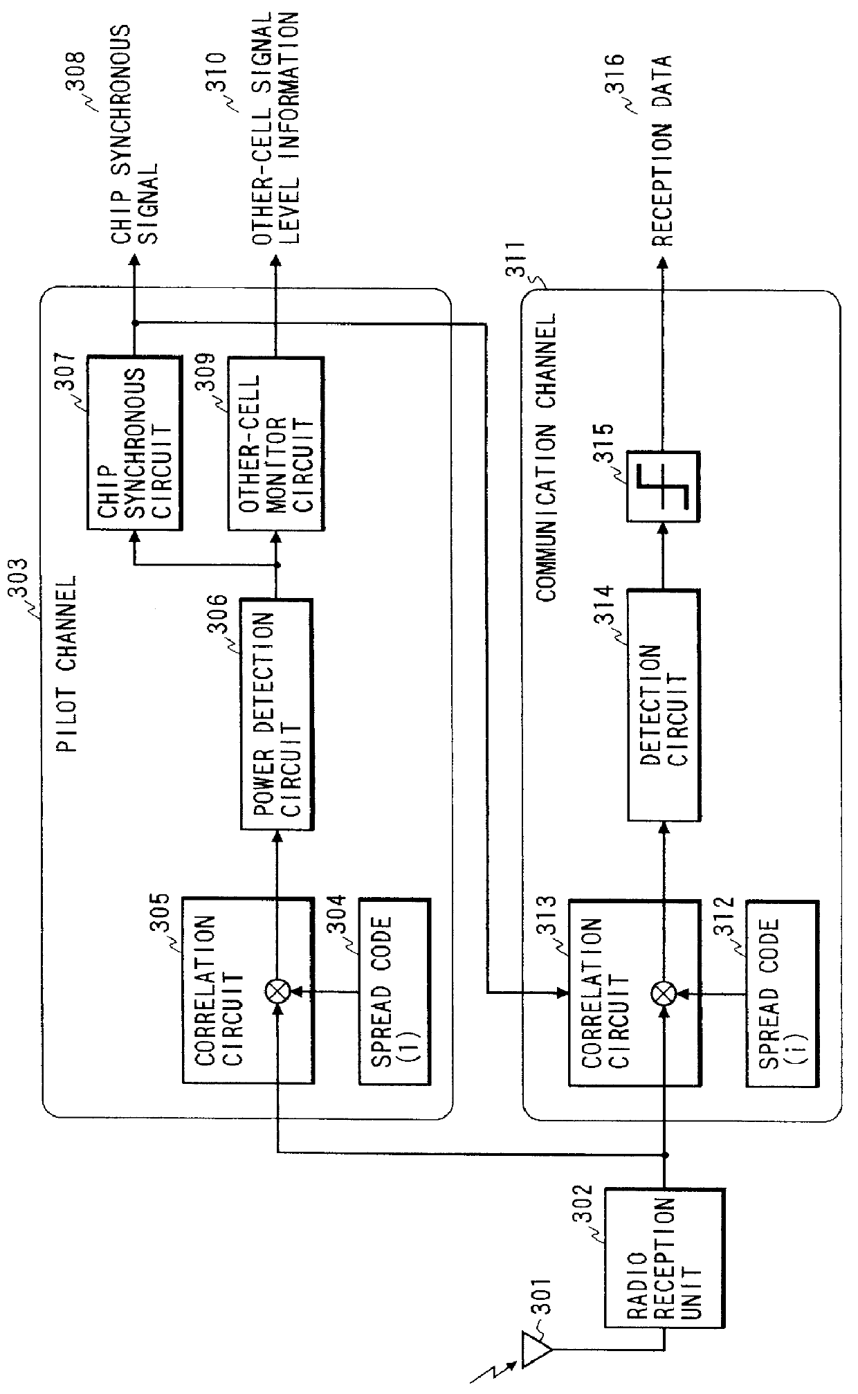
FIG. 3 a block diagram illustrating the structure of a mobile station in the cellular radio transmission system using the CDMA method according to Embodiment 3 of the invention. In FIG. 3, reference numeral 301 denotes an antenna; 302, radio reception unit; 303, a pilot channel; 304, a spread code (1); 305, a correlation circuit; 306, a power detection circuit; 307, a chip synchronous circuit; 308, a chip synchronous signal; 309, an other-cell monitor circuit; 310, other-cell signal level information; 311, communication channel; 312, spread code (i); 313, a correlation circuit; 314, a detection circuit; 315, a binary value decision circuit; and 316 reception data.

The operation of the mobile station according to this embodiment will be described. The signal received by the antenna 301 is down-converted in the radio reception unit 302. In the pilot channel 303, the signal is inversely spread with the spread code (1) 304 in the correlation circuit 305, and reception power is calculated...


PUM


Abstract

A base station transmits, in addition to a pilot channel, signals which are multiplexed with pilot symbols inserted in the respective signals in communication channels. As the transmission of the pilot channel as a reference signal for coherent detection is unnecessary with high power so as to attain high reliability, the pilot channel can be transmitted with low power by means of weight in comparison with the communication channel, so that interference with the communication channel of any other station is reduced. Moreover, accurate coherent detection can be made from the pilot symbol inserted in the communication channel on the mobile station side.

Description

1. Field of the InventionThe present invention relates to a CDMA cellular radio transmission system for use in digital cellular mobile communication and the like.2. Description of the Related ArtIn digital cellular mobile communication, a multiple access method means a line connection method when a plurality of stations simultaneously communicate with one another in the same band zone. CDMA, that is, Code Division Multiple Access is a technique in which multiple access is performed by means of spectrum spread communication for transmitting an information signal spectrum by spreading the spectrum over a band sufficiently wide in comparison with the original information band width and may also be called Spectrum Spread Multiple Access (SSMA). A direct spread method is a method of multiplying an information signal directly by a spread sequence code in the spread process.Of the detection method in digital communication, a coherent detection method has excellent static characteristics in...

Claims


Application Information

Patent Timeline
IPC IPC(8): H04B1/707H04B7/005H04B7/26H04B1/7073H04B1/7097H04J13/00H04W72/04
CPCH04B1/707H04B7/2637H04W52/32H04B1/7097H04B2201/70701Y02B60/50H04J13/16
Inventor MIYA, KAZUYUKIWATANABE, MASATOSHIKATO, OSAMU
Owner PANASONIC INTELLECTUAL PROPERTY CORP OF AMERICA
Why Eureka
Try Eureka