Camera capable of displaying the level of visual effect

a technology of visual effect and camera, applied in the field of cameras, can solve the problems of not taking into account the actual movement of the main subject, the inability of operators skilled and experienced, and the inability to visually predict the unsharpness of the background subject imag

Inactive Publication Date: 2000-08-01
MINOLTA CO LTD
View PDF20 Cites 3 Cited by
  • Summary
  • Abstract
  • Description
  • Claims
  • Application Information

AI Technical Summary

Benefits of technology

is to provide a camera capable of setting a variety of photographing conditions which allows a camera operator to sufficiently visualize what a final picture will look like, under the set photography conditions, before an exposure operation.

Problems solved by technology

With the existing cameras, it has been only possible for operators skilled and experienced in photography to obtain a final picture whose background image looks as unsharp as he / she desired by taking a picture only with a fixed focal length of the taking lens.
However, the depth of field impression described in the above publication is nothing but an index quantitatively indicating at what rate the image behind the main subject becomes unsharp in the final picture and does not take it into account how distant the background subject is from the main subject.
Therefore, it is quite difficult, if not impossible, to visually predict the unsharpness of the background subject image relative to the main subject image, that is, to what degree the main subject image stands out of the background subject image in the final picture.
However, this camera does not take actual movement of a main subject into account.

Method used


Image

  • Camera capable of displaying the level of visual effect
  • Camera capable of displaying the level of visual effect
  • Camera capable of displaying the level of visual effect

Examples


first embodiment

the invention will be described with reference to FIGS. 1 to 28.

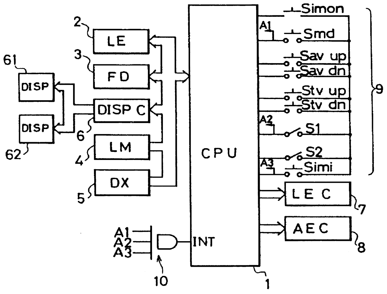
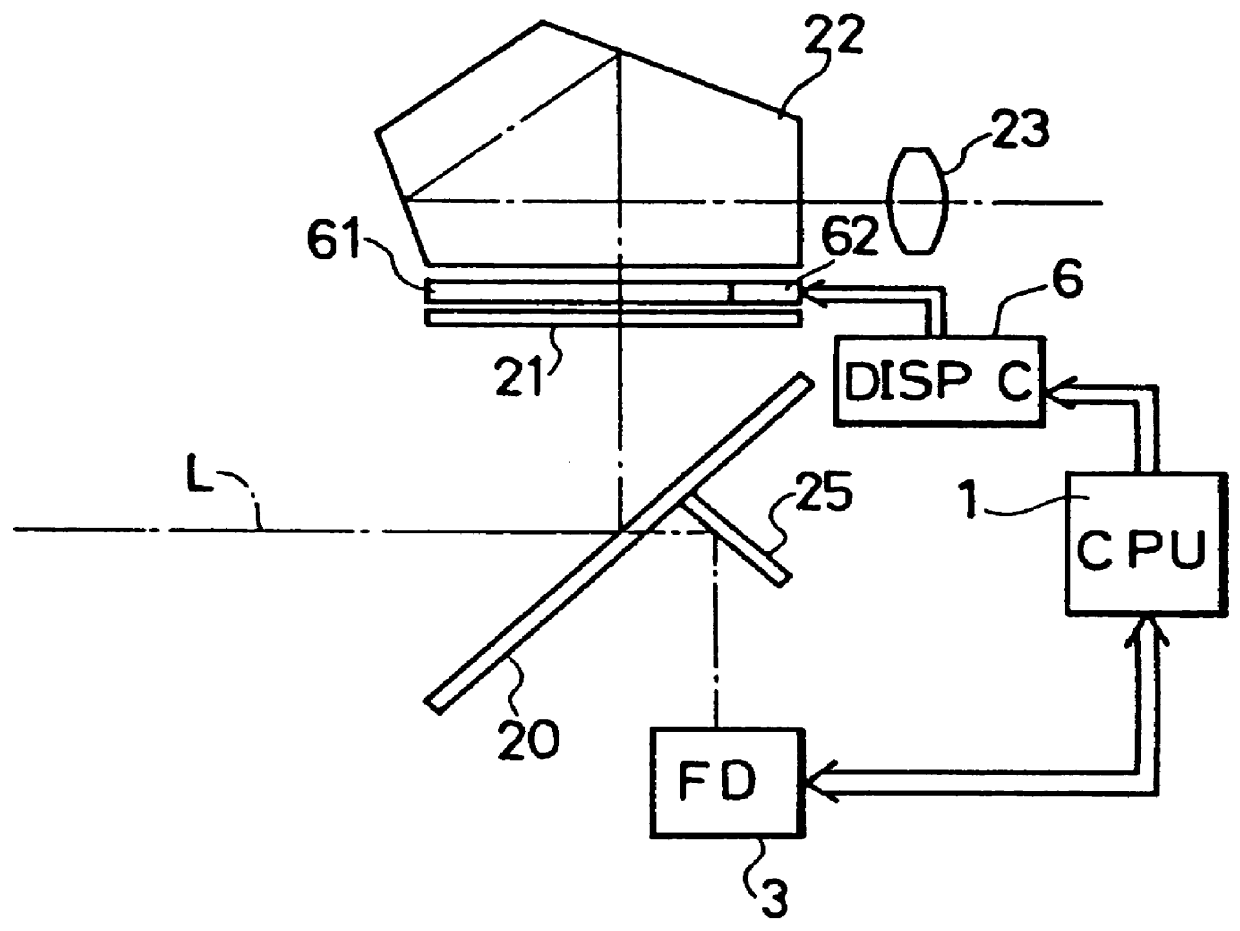
FIG. 2 is a diagram showing a main construction of a camera incorporating the invention as a first embodiment.

An image of a subject is introduced to a viewfinder mirror 20 along an optical axis L from an unillustrated taking lens. The viewfinder mirror 20 is opaque except a center portion thereof. The center portion of the mirror 20 is semitransparent such that only the subject image having an amount of light required for an automatic focusing control (hereinafter referred to as AF control) transmits therethrough. A focusing plate 21 is arranged in such a position to make sharpest a subject image introduced through the unillustrated taking lens unit disposed on the optical axis at the left side of the drawing in FIG. 2. On the focusing plate 21 is obtained the image as the one to be photographed. The subject image obtained on the focusing plate 21 is formed on an eyepiece lens 23 through a pentagonal prism 22. A camera ...


PUM


Abstract

A camera is provided with a photographing device for setting various photographing conditions which determine a state of a subject image to be obtained as a picture, the photograph device including an exposure device having a plurality of selectively settable exposure modes for automatically setting at least one exposure value based on brightness of a subject, a mode selector for selecting one of the plurality of exposure modes, a calculations unit for calculating an amount indicative of the state of the subject image in accordance with the photographing conditions set by the photography device, an estimation unit for estimating visual effects which the subject image provides based on the calculated state amount, and a display device for displaying the visual effect corresponding to the exposure mode selected by the mode selection means in accordance with the estimated visual effects. Accordingly, an operator of the camera is allowed to conceive before an exposing operation what the final picture will look like in accordance with the photographing conditions set in a variety of exposure modes.

Description

BACKGROUND OF THE INVENTION AND RELATED ART STATEMENT1. Field of the InventionThis invention relates to a camera and, more particularly to a camera capable of displaying the level of visual effects of a subject image which will be found in a final picture, as determined according to photographing settings.2. Description of the Prior ArtRecently, there has been known a camera provided with a plurality of exposure modes so that a camera operator can enjoy a variety of visual effects the camera can provide in taking pictures. Among such exposure modes are known a program mode in which photography settings such as aperture value AV and shutter speed TV are calculated in accordance with a preset program line, aperture priority mode and shutter speed priority mode in which the aperture value and shutter speed are manually settable respectively, and a manual mode in which both the aperture value and shutter speed are manually settable. Hereafter, the program mode, aperture priority mode, s...

Claims


Application Information

Patent Timeline
Patent Type & Authority Patents(United States)
IPC IPC(8): G03B13/18G03B13/30G03B7/08G03B17/20
CPCG03B7/0805G03B17/20G03B2207/005G03B2217/005G03B2217/185G03B7/097
Inventor HAMADA, MASATAKAKATOH, TAKEHIROTAMAI, KEIJISUZUKI, TATSUYA
Owner MINOLTA CO LTD
Why Eureka
Try Eureka