

Ultrasound probe
a technology of ultrasound probes and probes, applied in ultrasound therapy, sound producing devices, medical science, etc., can solve the problems of inapplicability of eye treatment design, eye pressure increase, eye damage,
- Summary
- Abstract
- Description
- Claims
- Application Information
AI Technical Summary
Benefits of technology
Problems solved by technology
Method used
Image

Examples
Embodiment Construction
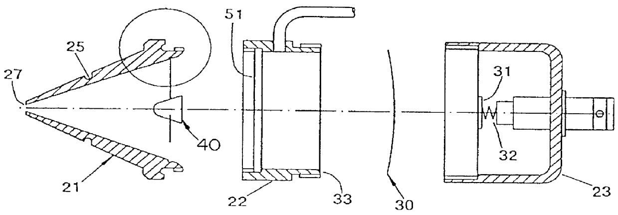
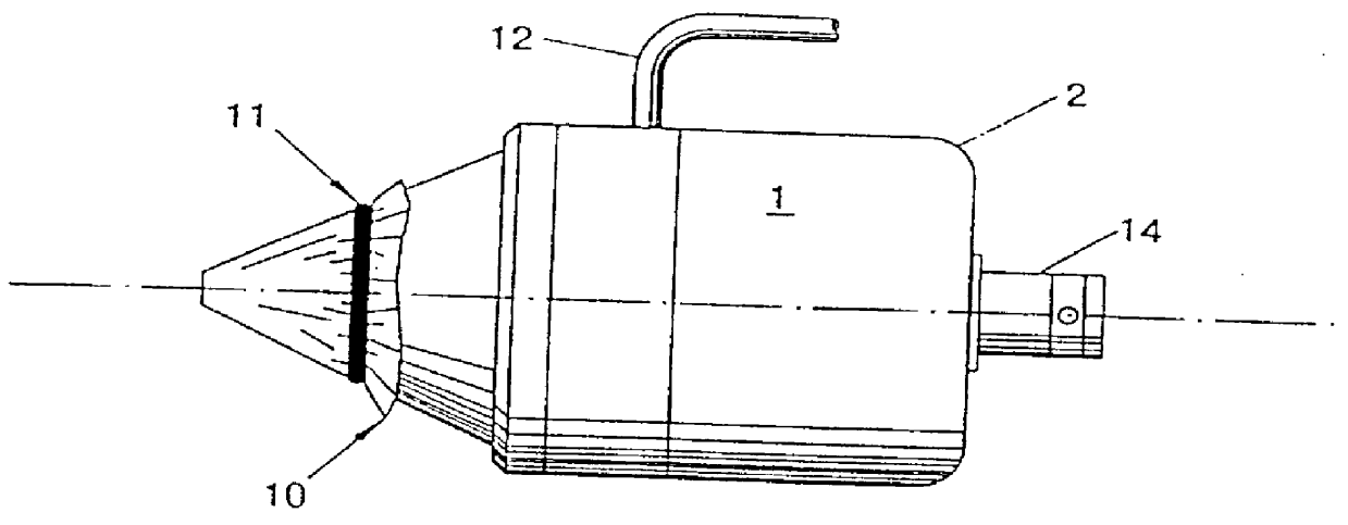
According to the present invention, an ultrasound device is disclosed, which can generate an adapted ultrasound field, applicable, for example, in an suggested method for treatment of glaucoma, which device can be directed towards the trabecular meshwork of an eye without affecting or harming the other parts of the sensitive eye in such a treatment.
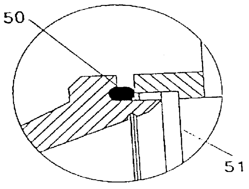
According to a first objective of the present invention, a body is inserted between the ultrasound crystal and an output port of the fluid filled portion of the device in order to centrally defocus the generated ultrasound and provide a reduced ultrasound field having a limited propagation of primarily higher intensities after passing the output port.
According to a second objective of the present invention, the casing is divided into several portions, whereby a forward conical front portion, including the output port and the centrally defocusing body, is easily replaceable, whereby fluid in the probe is refilled via a tube joint connected...
PUM
 Abstract
Description
Claims
Application Information