Electromagnetic-wave shielding and light transmitting plate

a technology of electromagnetic shielding and light transmission, applied in the direction of gas discharge vessels/containers, cathode ray tubes/electron beam tubes, transportation and packaging, etc., can solve the problems of electromagnetic wave affecting the operation of precision apparatus electromagnetic wave emission from these appliances has come into a problem, and electromagnetic wave affects the human body in a wrong way, etc., to achieve good electromagnetic-wave shielding efficiency, light transparency, and distinct pictures

Inactive Publication Date: 2001-07-17
BRIDGESTONE CORP
View PDF7 Cites 107 Cited by
  • Summary
  • Abstract
  • Description
  • Claims
  • Application Information

AI Technical Summary

Benefits of technology

It is an object of the present invention to solve the above conventional problems and to provide an electromagnetic-wave shielding and light transmitting plate suitable for an electromagnetic-wave shielding filter for a PDP, which has good electromagnetic-wave shielding efficiency and light transparency, can provide distinct pictures, and can yet be easily made.
The electromagnetic-wave shielding and light transmitting plate of the eighth aspect can be easily made by interposing two adhesive films, in which a suitable amount of crosslinking agent for heat curing or photo-curing is mixed to a resin such as EVA, and the conductive mesh member which is disposed therebetween, between the transparent base plates 92A and 92B, then decompressing and deaerating them under the heated condition, and hardening the adhesive layer by heating or irradiation to integrate them.

Problems solved by technology

Recently, with the spread of electronic appliances including office automation apparatuses and communication instruments, electromagnetic wave emission from these appliances have come into a problem.
That is, adverse effect of electromagnetic wave to the human body is feared and it is also a problem that the electromagnetic wave affects precision apparatus to operate in a wrong way.
Further, a phenomenon that the dots of the PDP and the grids of the mesh member produce interference fringes (so-called "moire") also occurs and this phenomenon also makes the pictures unseemly.
The conventional electromagnetic-wave shielding and light transmitting plate has a disadvantages in that reflection of light on a display makes the pictures unseemly and in that the angle of visibility is small so that images on the display are not visible due to lateral incident light.
Moreover, there is a problem that heat from the main body of an office automation apparatus results in overheating of the display.

Method used


Image

  • Electromagnetic-wave shielding and light transmitting plate
  • Electromagnetic-wave shielding and light transmitting plate
  • Electromagnetic-wave shielding and light transmitting plate

Examples


examples 1 through 4

,

Comparative Examples 1 through 3

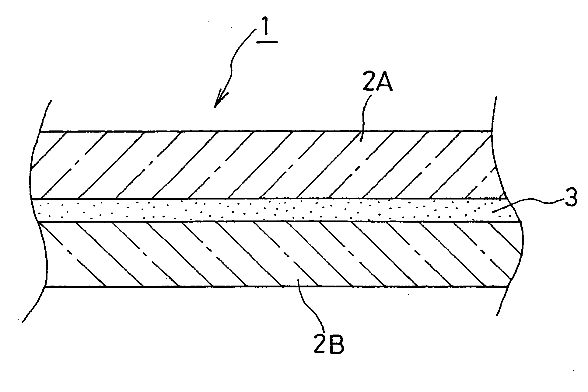
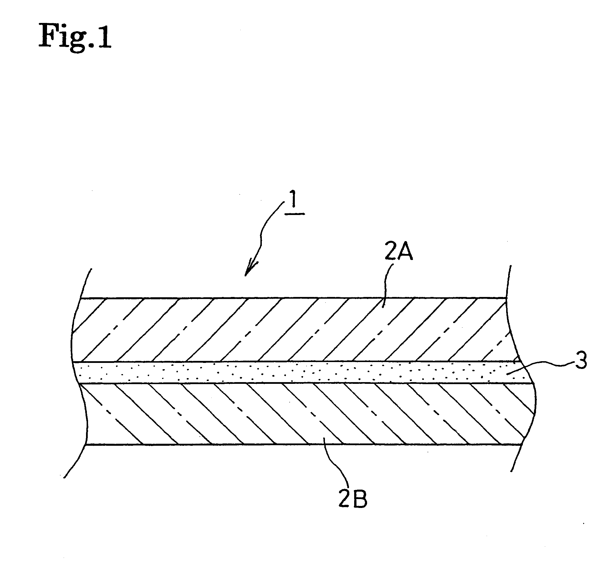
Used as the front transparent base plate 2A was a glass plate having a thickness of 3.0 mm and used as the rear transparent base plate 2B was a PET sheet having a thickness of 0.1 mm these plates having an adhesive sheet posed therebetween were entered into a rubber bag which was then vacuumed to be deaerated and pre-compressed by beating them at 85.degree. C. for 15 minutes. After that, the object thus pre-compressed was entered into an oven and heated at 150.degree. C. for 15 minutes so that it is crosslinked and hardened to be integrated.

In each of Comparative Examples 2, 3 and Examples 3, 4, a conductive mesh member specified in Table 1 was further interposed between the transparent base plates before integrated.

The resultant plate were measured for the respective electromagnetic-wave shielding effect in a range between 30 MHz and 300 MHz, its light transmittance, and its visibility (the presence or absence of moire phenomenon) in the following m...

examples 5 , 6

Examples 5, 6

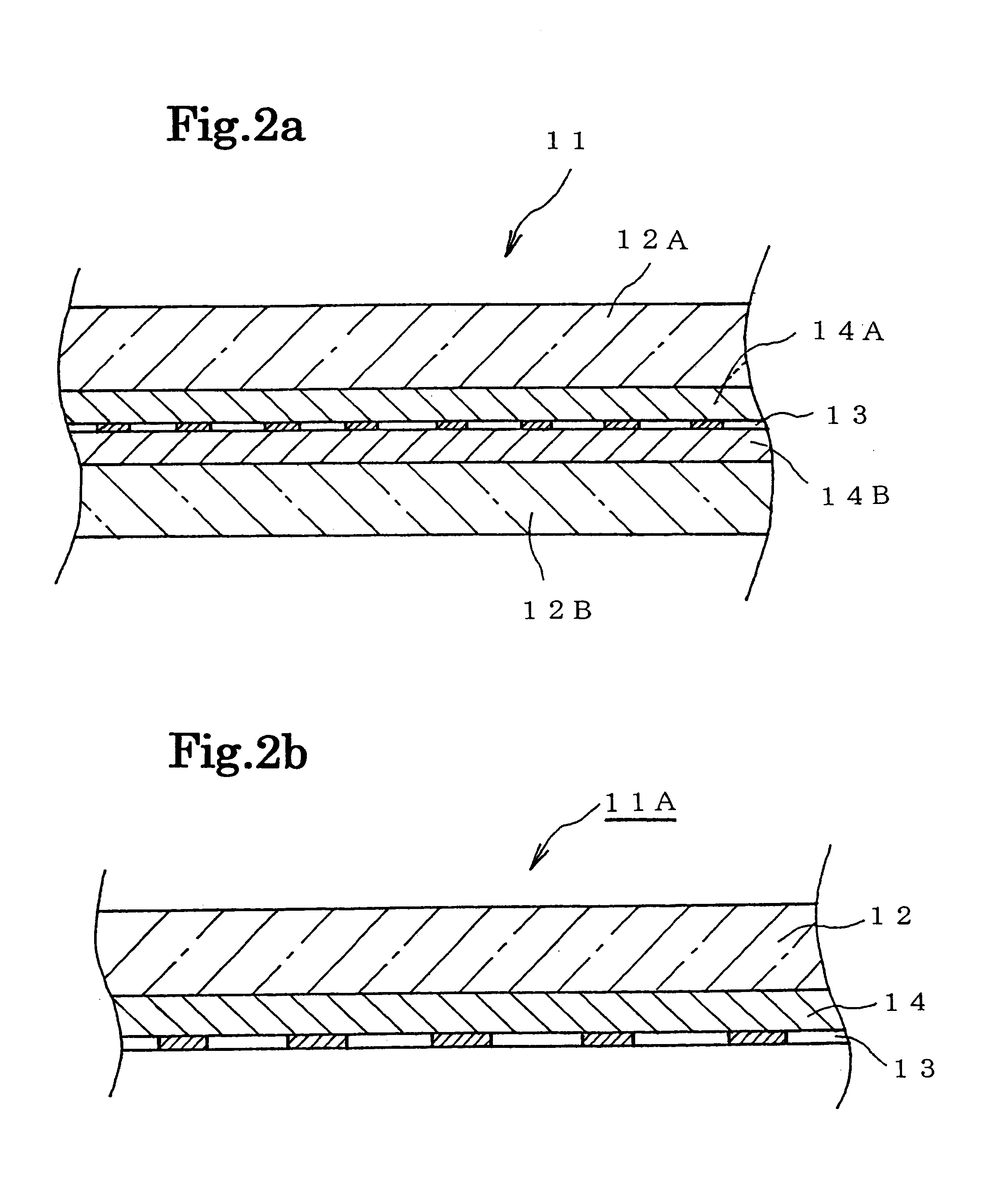
Used as the front transparent base plate 12A was a glass plate having a thickness of 3.0 mm and used as the rear transparent base plate 12B was a PET sheet having a thickness of 0.1 mm. These plates 12A, 12B having a metallic film specified in Table 2 interposed between two adhesive sheets which were interposed between the plates were entered into a rubber bag which was then vacuumed to be deaerated and pre-compressed by heating them at 85.degree. C. for 15 minutes. After that, the object thus pre-compressed was entered into an oven and heated at 150 .degree. C for 15 minutes so that it is crosslinked and hardened to be integrated.

The resultant plate was measured for its electromagnetic-wave shielding effect in a range between 30 MHz and 300 MHz, its light transmittance, and its visibility (the presence or absence of moire phenomenon) in the same manner as the fist aspect The results are tabulated in Table 2.

examples 7 , 8

Examples 7, 8

Used as the front transparent base plate 42A was a glass plate having a thickness of 3.0 mm which was formed with a metallic film of metal specified in Table 4 on one surface thereof and then pattern etched in patterns specified in Table 4. Used as the rear transparent base plate 42B was a PET sheet having a thickness of 0.1 mm.

These plates 42A, 42B having an adhesive film interposed therebetween were entered into a rubber bag which was then vacuumed to be deaerated and pre-compressed by heating them at 85.degree. C. for 15 minutes. After that, the object thus pre-compressed was entered into an oven and heated at 150.degree. C. for 15 minutes so that it is crosslinked and hardened to be integrated.

The resultant plate was measured for its electromagnetic-wave shielding effect in a range between 30 MHz and 300 MHz, its light transmittance, and its visibility (the presence or absence of moirephenomenon) in the same manner as the first aspect. The results are tabulated in T...


PUM


Abstract

An electromagnetie-wave shielding and light transmitting plate suitable for an electromagnetic-wave shielding filter for a PDP, which has good electromagnetic-wave sheilding efficiency and light transparency, can provide distinct pictures, and can yet be easily made, is provided. The electromagnetic-wave shielding and light transmitting plate is formed of two transparent base plates and an adhesive layer made of EVA in which conductive particles are dispersed and mixed. The base plates are integrally bonded together by the adhesive layer. Adjusting the particle size and the dispersed amount of the conductive particles enables the manufacture of plates having desired electromagnetic-wave shielding efficiency, in addition, good light transparency, without moire phenomenon. Using an adhesive sheet formed by mixing the conductive particles into the EVA facilitates the manufacture of the aforementioned plate.

Description

The present invention relates to an electromagnetic-wave shielding and light transmitting plate and, more particularly, to an electromagnetic-wave shielding and light transmitting plate suitable for a front filter for a PDP (plasma display panel), which has good electromagnetic-wave shielding efficiency and light transparency.Recently, with the spread of electronic appliances including office automation apparatuses and communication instruments, electromagnetic wave emission from these appliances have come into a problem. That is, adverse effect of electromagnetic wave to the human body is feared and it is also a problem that the electromagnetic wave affects precision apparatus to operate in a wrong way.In particular, a PDP, which is merchandised as a flat large display in current years, has large electromagnetic wave emission due to its operating mechanism.Therefore, plates having good electromagnetic-wave shielding efficiency and light transparency have developed and come into pra...

Claims


Application Information

Patent Timeline
Patent Type & Authority Patents(United States)
IPC IPC(8): H01J29/86H01J17/49H05K9/00
CPCH01J11/10H01J11/44H01J29/868H05K9/0096Y10T428/24876H01J2229/8633Y10T428/24868H01J2211/446
Inventor YOSHIKAWA, MASATOSAITO, SHINJIMORIMURA, YASUHIRO
Owner BRIDGESTONE CORP
Why Eureka
Try Eureka