Exhaust pipe joint assembly

a technology of exhaust pipe and assembly, which is applied in the direction of adjustable joints, mechanical devices, machines/engines, etc., can solve the problems of large starting torque to generate bending displacement, noise, and large sliding resistan

Inactive Publication Date: 2002-07-16
HONDA MOTOR CO LTD +1
View PDF15 Cites 18 Cited by
  • Summary
  • Abstract
  • Description
  • Claims
  • Application Information

AI Technical Summary

Benefits of technology

It is also possible to dispose the first ball joint portions and the second ball joint portions in the same position in the longitudinal direction of the joint pipes. In such as arrangement, however, it is necessary to form a large notch in the periphery of each of the joint pipes in a portion corresponding to the ball receiving portions of the other of the joint pipes in order to avoid interference of the two joint pipes. As a result, the rigidity of the joint pipes becomes lower and there is a possibility that the joint pipes and the coupling piece become rickety. As a solution, preferably, the first ball joint portions and the second ball joint portions are disposed at a distance from each other in the longitudinal direction of the joint pipes. Then, there is no need of forming the notch in the periphery of the joint pipe. Even if there is such a need, the notch may be kept small to the extent possible. Therefore, the rigidity of the joint pipes can be secured and the disadvantage in that the joint pipes and the coupling piece become rickety can be prevented.

Problems solved by technology

The vibrations are in turn transmitted to a motor vehicle body through a supporting member of the exhaust pipe, thereby resulting in the occurrence of noises.
However, since spherical sliding surfaces of a sealing member (gasket) and of a spherical flange are being forcibly urged toward each other, a sliding resistance becomes large.
As a result, the starting torque to generate a bending displacement is large.
In addition, there were cases in which exhaust gases leaked to some extent through the in sliding surfaces.
However, when the engine largely moves due to a torque reaction force, inertia force, or the like, relative to the vehicle body, the amounts of extension and contraction as well as of bending of the bellows pipe becomes excessive if the bellows pipe is small in length.
As a consequence, there is a problem in that the joint made up of the bellows pipe is inferior to the spherical joint in points of cost, weight, and space to be occupied thereby.
Further, by the interference of the coupling piece with each of the joint pipes, the bending displacement of both the joint pipes is restricted to a predetermined range.
As a result, undue stresses are not operated on the bellows pipe.
As a result, the rigidity of the joint pipes becomes lower and there is a possibility that the joint pipes and the coupling piece become rickety.
Therefore, the rigidity of the joint pipes can be secured and the disadvantage in that the joint pipes and the coupling piece become rickety can be prevented.

Method used


Image

  • Exhaust pipe joint assembly
  • Exhaust pipe joint assembly
  • Exhaust pipe joint assembly

Examples


Embodiment Construction

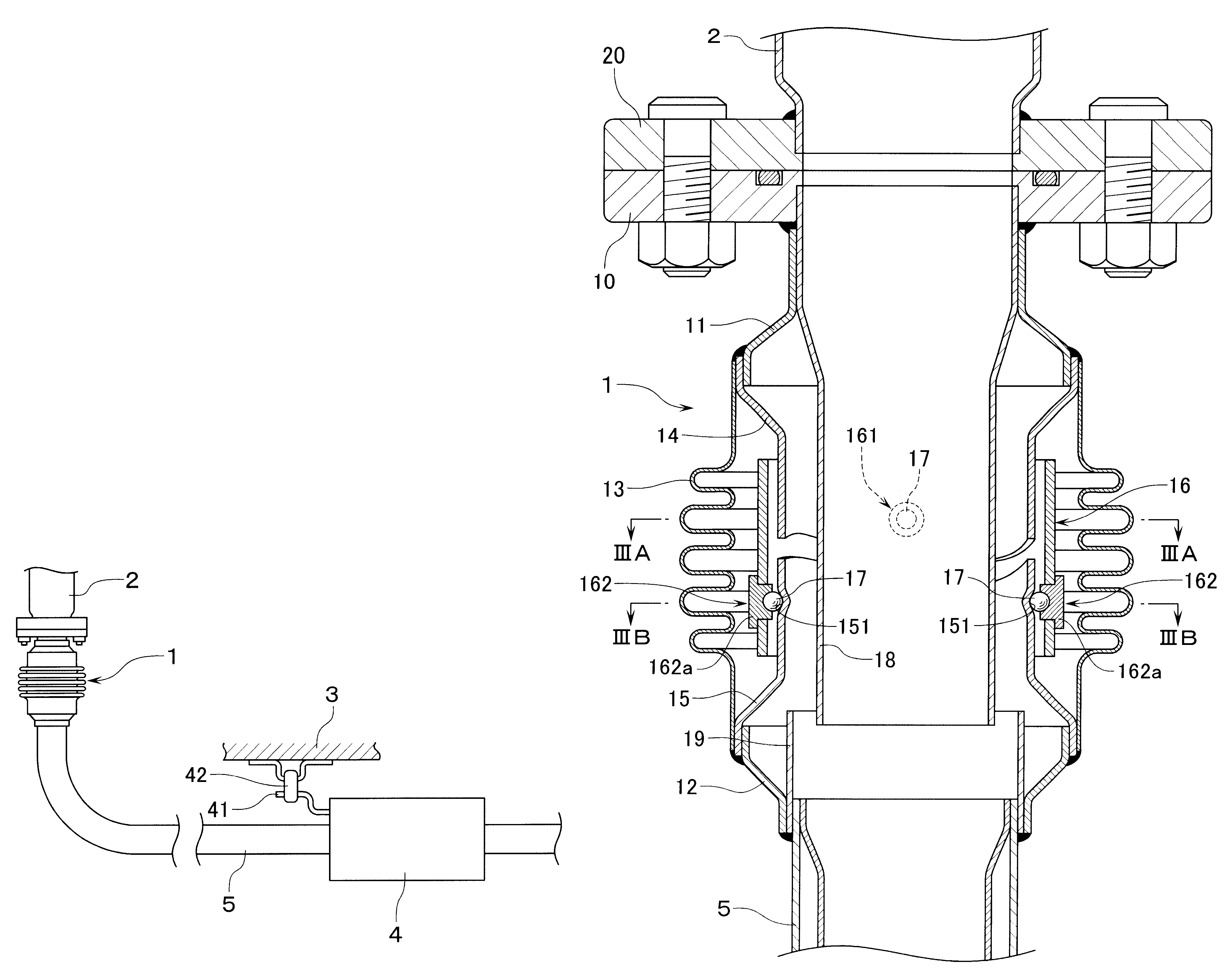
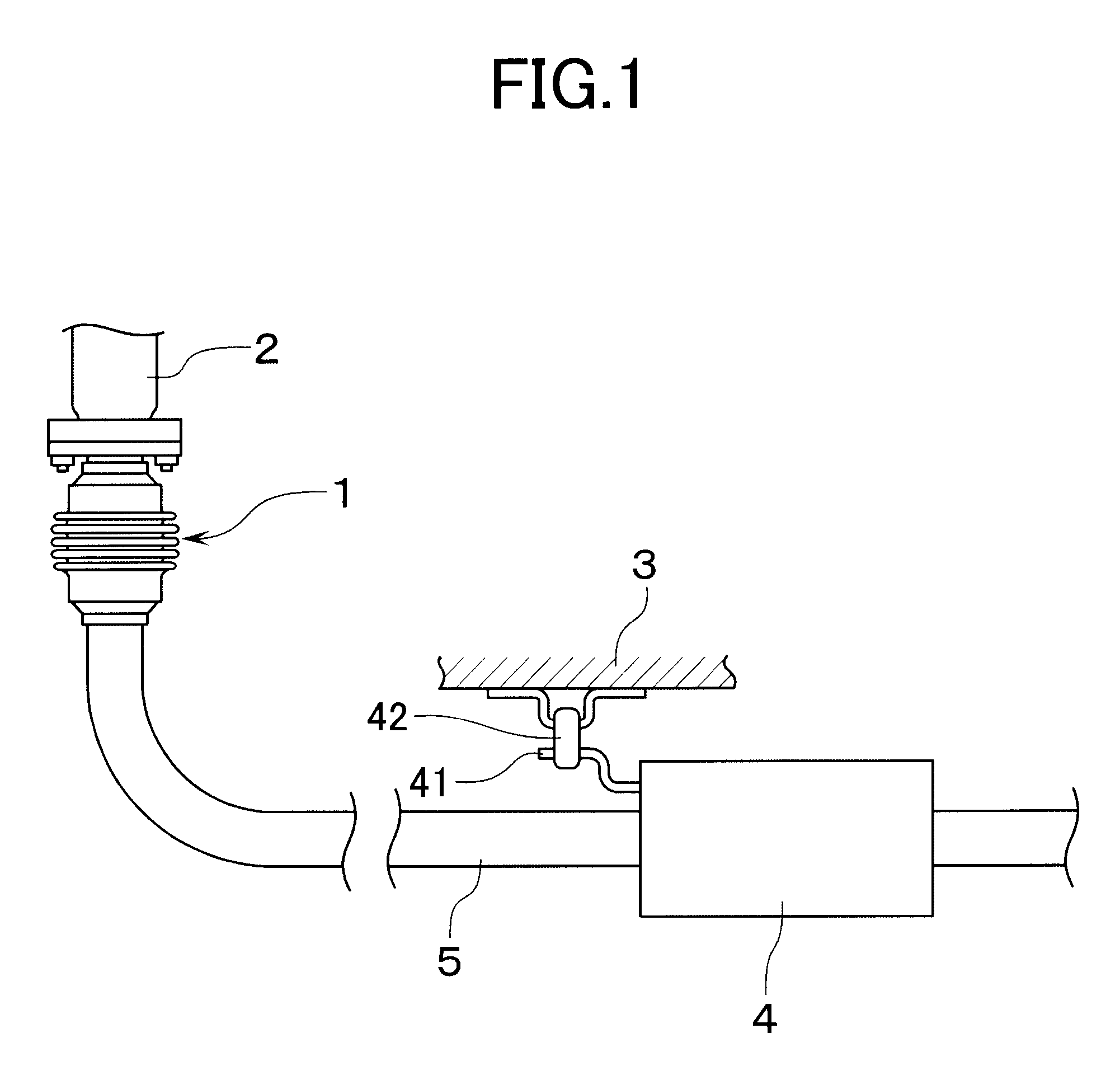
As shown in FIG. 1, an exhaust pipe joint assembly 1 according to the present invention is interposed in an exhaust-gas system of an engine for a motor vehicle in a manner to connect an exhaust manifold 2, which is an upstream exhaust pipe, and a downstream exhaust pipe 5 which is communicated with a silencer 4 disposed under a floor 3 of a vehicle body. The silencer 4 is supported under the floor 3 by means of a mounting rubber 42 through which is passed a stay 41 which is in the shape of a bar and is fixed to the silencer 4.

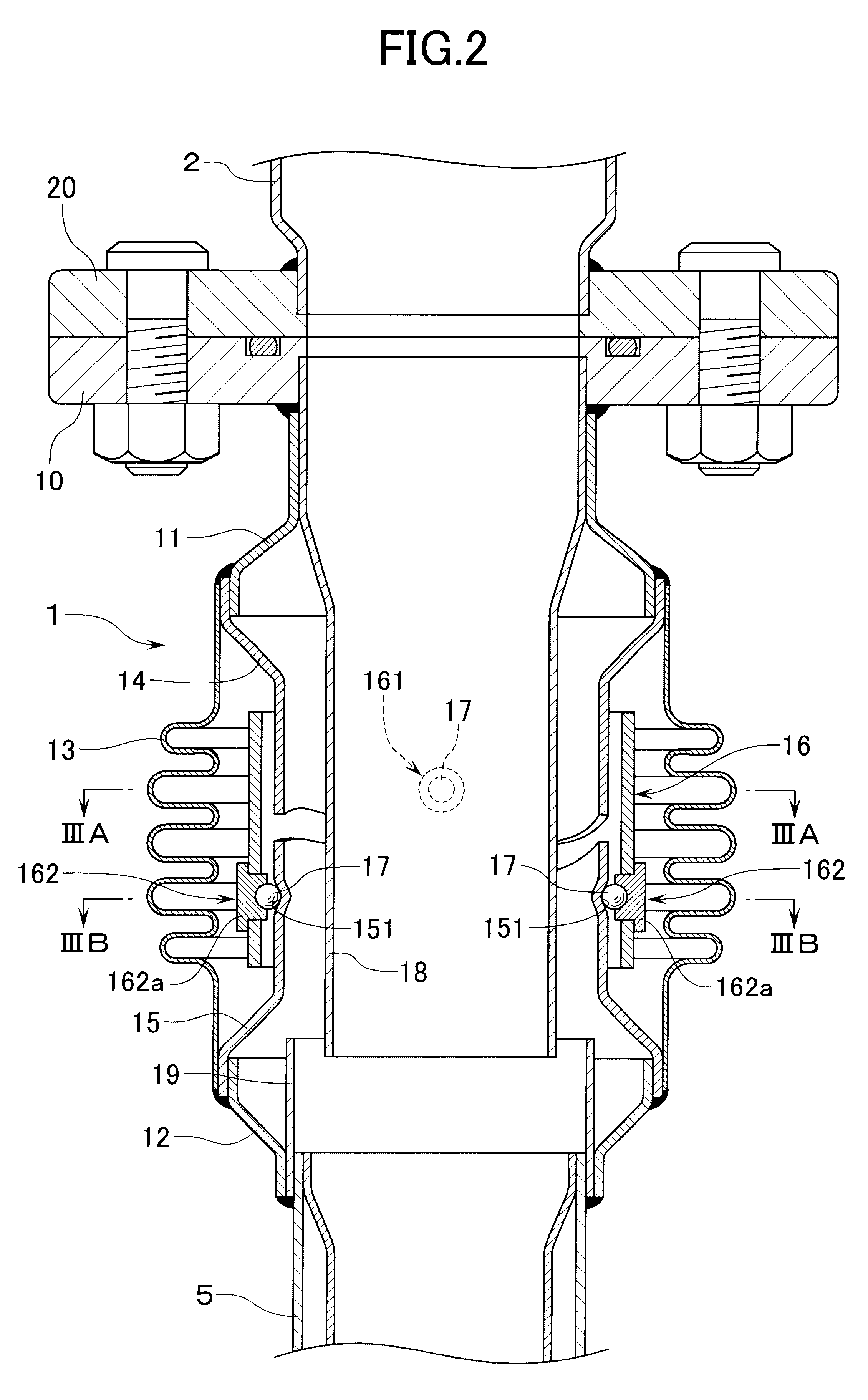
With reference to FIG. 2, the exhaust pipe joint assembly 1 is provided with a flange 10 which is mated with a flange 20 on a downstream end of the exhaust manifold 2. The exhaust pipe joint assembly 1 is further provided with a bellows pipe 13. One end of the bellows pipe 13 is welded to an upstream connecting pipe 11 which is connected to the flange 10, and the other end of the bellows pipe 13 is welded to a downstream connecting pipe 12 which is welded to an...


PUM


Abstract

An exhaust pipe assembly provided with a bellows pipe for connecting an upstream exhaust pipe and a downstream exhaust pipe is disposed so as to form a double pipe construction with a first joint pipe which is connected to the upstream exhaust pipe and a second joint pipe which is connected to the downstream exhaust pipe. A pair of ball receiving portions are disposed on a peripheral surface of the first joint pipe at a distance from each other in a circumferential direction, and a pair of ball receiving portions are disposed on a peripheral surface of the second joint pipe at a distance from each other in a circumferential direction. The ball receiving portions are disposed at an angular phase difference with each other in the circumferential direction. There is provided a coupling piece which has a pair of first ball joint portions engaged with the pair of ball receiving portions of the first joint pipe through a ball, and a pair of second ball joint portions engaged with the pair of ball receiving portions of the second joint pipe respectively through a ball.

Description

1. Field of the InventionThe present invention relates to an exhaust pipe joint assembly (i.e., a joint assembly for connecting exhaust pipes together) which is interposed in an exhaust-gas system mainly of an engine for a motor vehicle such that an exhaust pipe on an upstream side (hereinafter also called "an upstream exhaust pipe") and an exhaust pipe on a downstream side (hereinafter also called "a downstream exhaust pipe") can be connected in a manner to be relatively displaceable by bending.2. Description of Related ArtAn exhaust pipe which is disposed in an exhaust-gas system of an engine for a motor vehicle receives the transmission of vibrations of the engine. The vibrations are in turn transmitted to a motor vehicle body through a supporting member of the exhaust pipe, thereby resulting in the occurrence of noises.In order to solve this kind of problem, there has hitherto been known an exhaust pipe joint assembly having interposed in an exhaust-gas system of an engine a sph...

Claims


Application Information

Patent Timeline
Patent Type & Authority Patents(United States)
IPC IPC(8): F01N7/18F16L27/10F16L27/00F16L27/11F01N13/18F01N13/08F16L27/08
CPCF01N13/1816F16L27/1004F16L27/11
Inventor UEGANE, MASAYUKIAKIYAMA, HIDEKAZUKOINUMA, KAZUNORITAKIZAWA, KAZUTOSHINAITOU, TAKAHIKOSUZUKI, HIDENORI
Owner HONDA MOTOR CO LTD
Why Eureka
Try Eureka