Pressure sensor for detecting differential pressure between two spaces

a pressure sensor and differential pressure technology, applied in the direction of fluid pressure measurement, pressure difference measurement between multiple valves, instruments, etc., can solve the problems of increasing the cost of manufacturing the pressure sensor, difficult to miniaturize the cavity, and complex sensor constitution as a whol

Inactive Publication Date: 2003-04-22
DENSO CORP
View PDF8 Cites 58 Cited by
  • Summary
  • Abstract
  • Description
  • Claims
  • Application Information

AI Technical Summary

Problems solved by technology

It is therefore difficult to miniaturize the cavity for performing positioning between the hole and the cavity.
In this pressure sensor, however, the sensor constitution is complicated as a whole.
This results in increased cost for manufacturing the pressure sensor.

Method used


Image

  • Pressure sensor for detecting differential pressure between two spaces
  • Pressure sensor for detecting differential pressure between two spaces
  • Pressure sensor for detecting differential pressure between two spaces

Examples


second embodiment

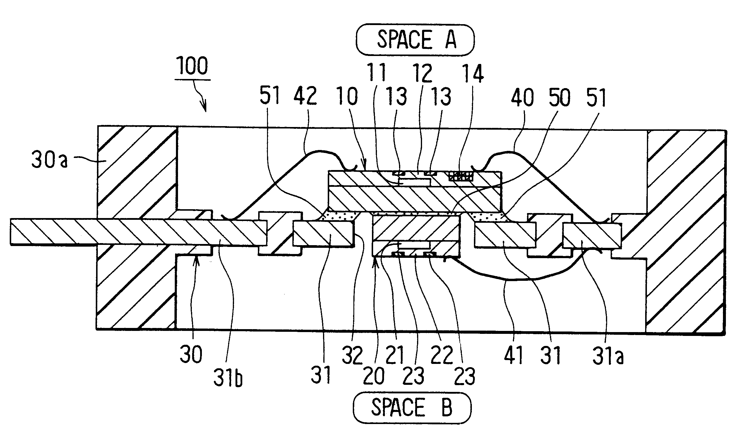
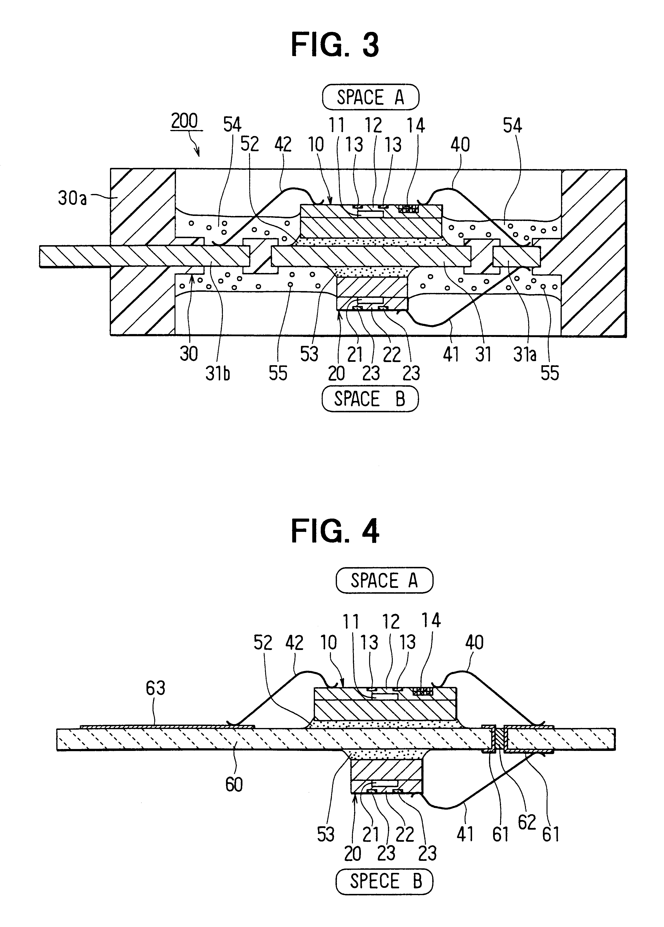
FIG. 3 shows a pressure sensor 200 in a second preferred embodiment of the present invention. In the second embodiment, the resin substrate 30 does not have the hole 32 as in the first embodiment. The sensor elements 10, 20 are respectively attached to both surfaces of the resin substrate 30 at the back surfaces not having the diaphragms 12, 22. The other features are substantially the same as those in the first embodiment. The same parts and components as those in the first embodiment are indicated by the same reference numerals, and the same explanation will not be reiterated.

As shown in FIG. 3, the back surface of the first sensor element 10 disposed in the pressure space A is bonded to one surface of the lead frame 31 through adhesive 52 made of, for instance, resin. The back surface of the second sensor element 20 disposed in the pressure space B is bonded to the other surface of the lead frame 31 through adhesive 53 made of, for instance, resin. Accordingly, the pressure senso...

third embodiment

The plate member for partitioning the pressure spaces A, B is not limited to the resin substrate 30 into which the lead frame 31 is insert-molded, but may by a ceramic substrate or the like. In this case, a through hole is formed in the ceramic substrate to allow electrical communication between electrical signals respectively taken out from two sensor elements via wires. FIG. 4 shows an example in which academic substrate 60 is utilized.

The ceramic substrate 60 has conductive thick films 61, which are formed on both surfaces of the substrate 60 and connected to each other via a wall surface of a through hold formed in the substrate 60. Reference numeral 62 denotes a conductive member (solder) filling the through hole 62. The conductive thick films 61 are made of copper or the like. Further, a conductive thick film 63 is formed on the surface of the ceramic substrate 60 at a side of the pressure space A to output the signal taken out through the wire 42. The members 61-63 form elect...


PUM

PropertyMeasurementUnit
pressureaaaaaaaaaa
pressuresaaaaaaaaaa
electricallyaaaaaaaaaa

Abstract

A pressure sensor has two sensor elements respectively disposed in different pressure spaces A and B. Each of the sensor elements has a semiconductor substrate having a pressure reference chamber therein, a diaphragm formed as a wall defining the pressure reference chamber, and gauges for converting deformation of the diaphragm into an electric signal. The two sensor elements overlap with each other at sides opposite to the respective diaphragms, and close a hole formed in a partition member partitioning the two pressure spaces A and B. A differential pressure between the pressure spaces A and B is detected as a relative pressure by a difference between outputs from the two sensor elements.

Description

1. Field of the InventionThis invention relates to a pressure sensor for detecting a differential pressure between two spaces as a relative pressure.2. Description of the Related ArtJP-A-8-236788 discloses a pressure sensor for detecting a relative pressure. The pressure sensor has a substrate having a micro cavity therein and a hole formed from the back surface of the substrate to communicate with the micro cavity. In this constitution, however, it is necessary to use an alignment apparatus for determining the position of the micro cavity from the back surface of the substrate. In addition, when the hole is formed by anisotropic etching, dimensional variation of the etched hole is large. It is therefore difficult to miniaturize the cavity for performing positioning between the hole and the cavity.To solve these problems, JP-A-5-52691 proposes a pressure sensor, which can detect a differential pressure by using two pressure sensitive elements to thereby determine a relative pressure...

Claims


Application Information

Patent Timeline
Patent Type & Authority Patents(United States)
IPC IPC(8): G01L9/00G01L15/00G01L13/06H01L29/84
CPCG01L15/00G01L19/146G01L19/147H01L2924/1305H01L2224/48227H01L2224/73265H01L2224/48472H01L2224/32225H01L2224/48091H01L2924/13091H01L2924/00014H01L2924/00
Inventor TOYODA, INAOSUZUKI, YASUTOSHI
Owner DENSO CORP
Why Eureka
Try Eureka