System and method for monitoring incoming communications to a telecommunications device

a telecommunications device and incoming communication technology, applied in the field of communication, can solve the problems of incoming call not being completed, phone line not being able to receive incoming calls to the home pc user's residential premises, and calling party receiving a busy signal

Inactive Publication Date: 2003-12-16
BELLSOUTH INTPROP COR
View PDF11 Cites 153 Cited by
  • Summary
  • Abstract
  • Description
  • Claims
  • Application Information

AI Technical Summary

Problems solved by technology

Therefore, when the home PC user is connected to the Internet via the single telephone line, the telephone line is not capable of receiving incoming calls to the home PC user's residential premises.
Thus, if the home PC user receives an incoming call from a calling party during the course of an Internet session, the incoming call is not be completed and the calling party receives a busy signal.
Moreover, conventional call-waiting services cannot remedy this problem because conventional call-waiting services must be disabled during an Internet session due to the fact that the conventional call-waiting signal would disrupt data transfer over the Internet via the single telephone line to the residential premises.
New inconveniences arise, however, for many home PC users with a two-line configuration.
Significantly, for a home PC user who subscribes to a caller ID service whereby the name and telephone number of a calling party are displayed on a visual display unit associated telephone line / device, when the home PC user receives an incoming call during an Internet session, the PC user cannot easily access the visual display unit in enough time to answer the incoming call after viewing the displayed name of the calling party unless the visual display unit is in extremely close proximity to the home PC user's PC.
This dilemma is especially vexing for residential premises in which the home PC and telephone are located in separate rooms or on separate floors.

Method used


Image

  • System and method for monitoring incoming communications to a telecommunications device
  • System and method for monitoring incoming communications to a telecommunications device
  • System and method for monitoring incoming communications to a telecommunications device

Examples


Embodiment Construction

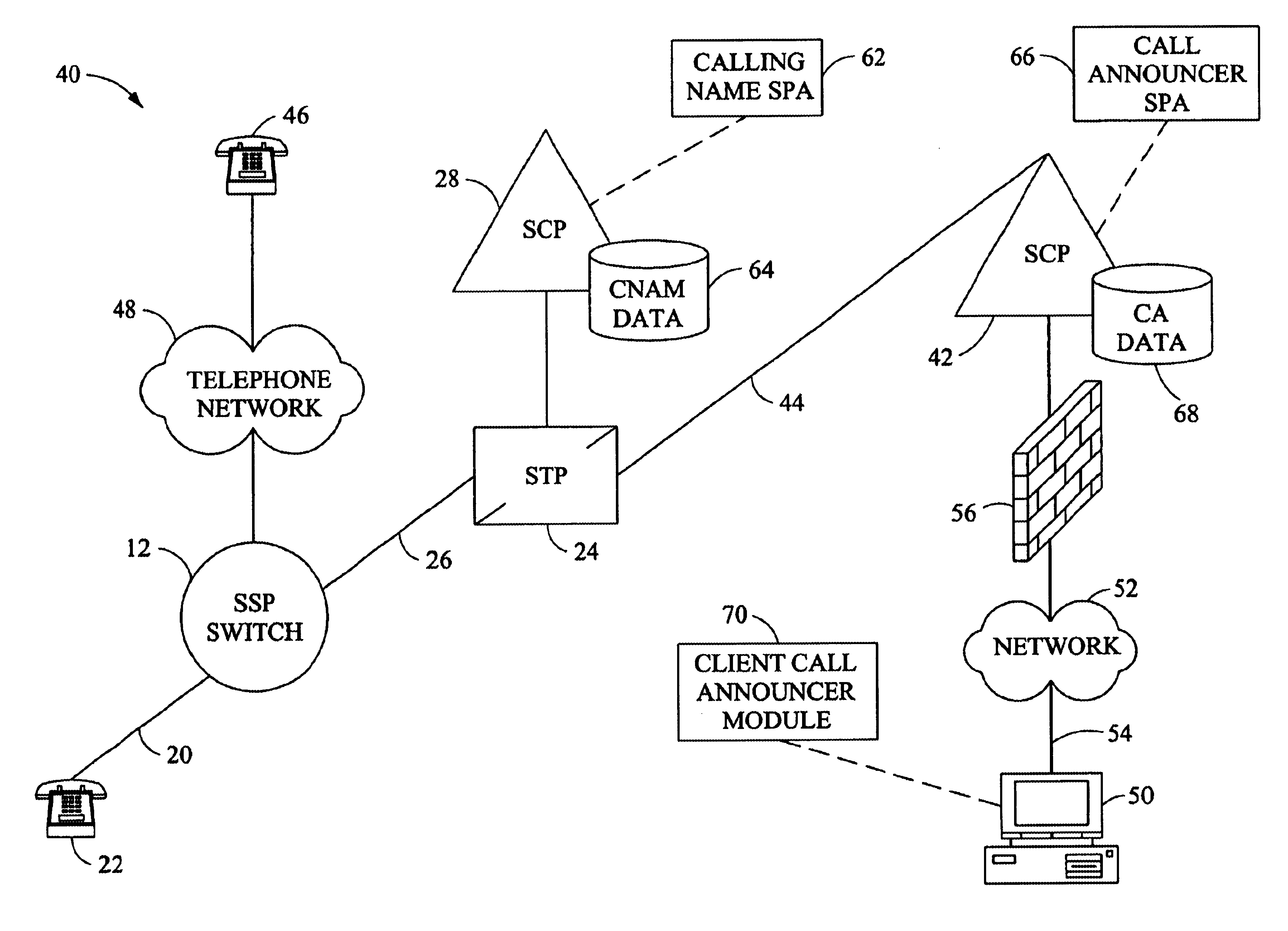
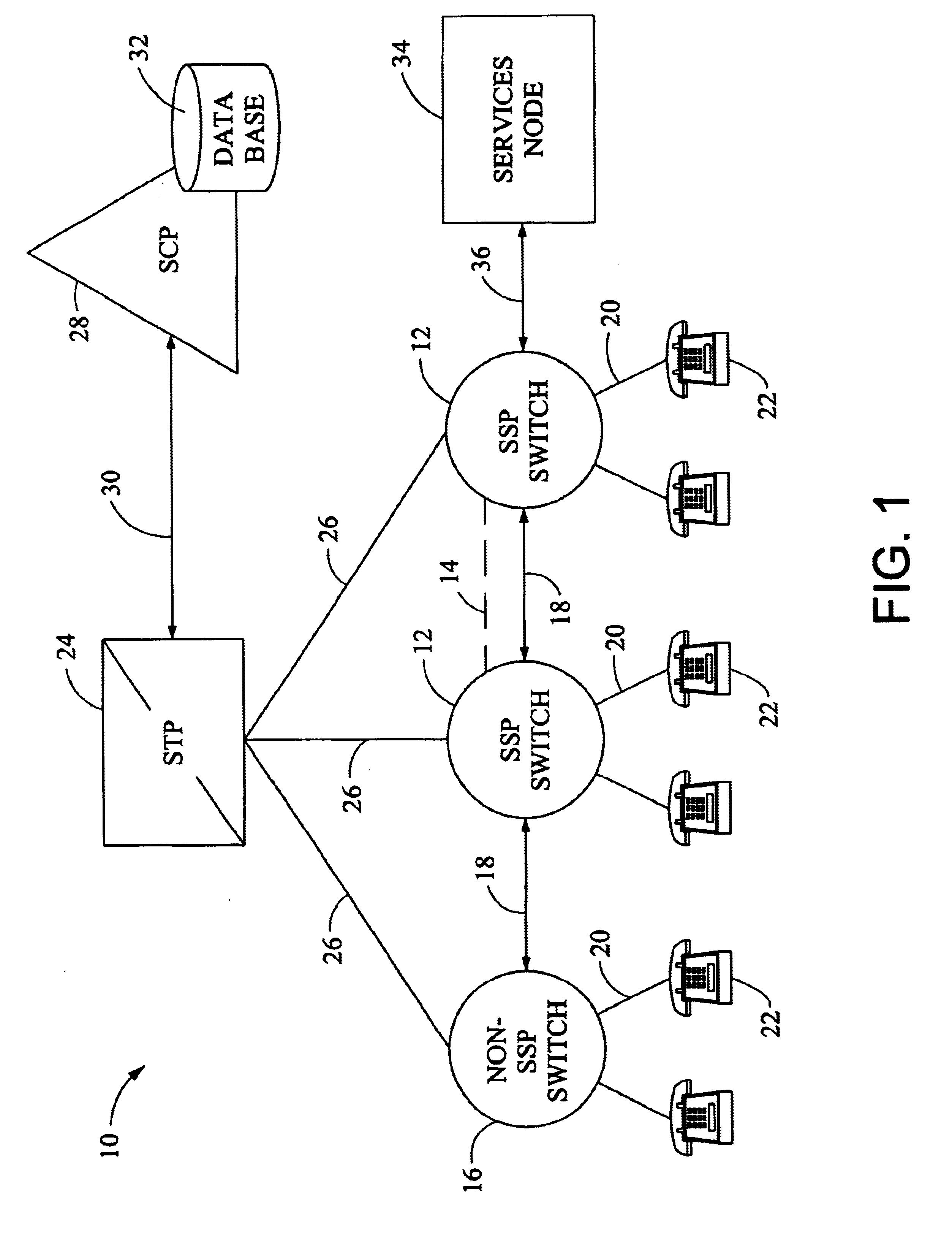
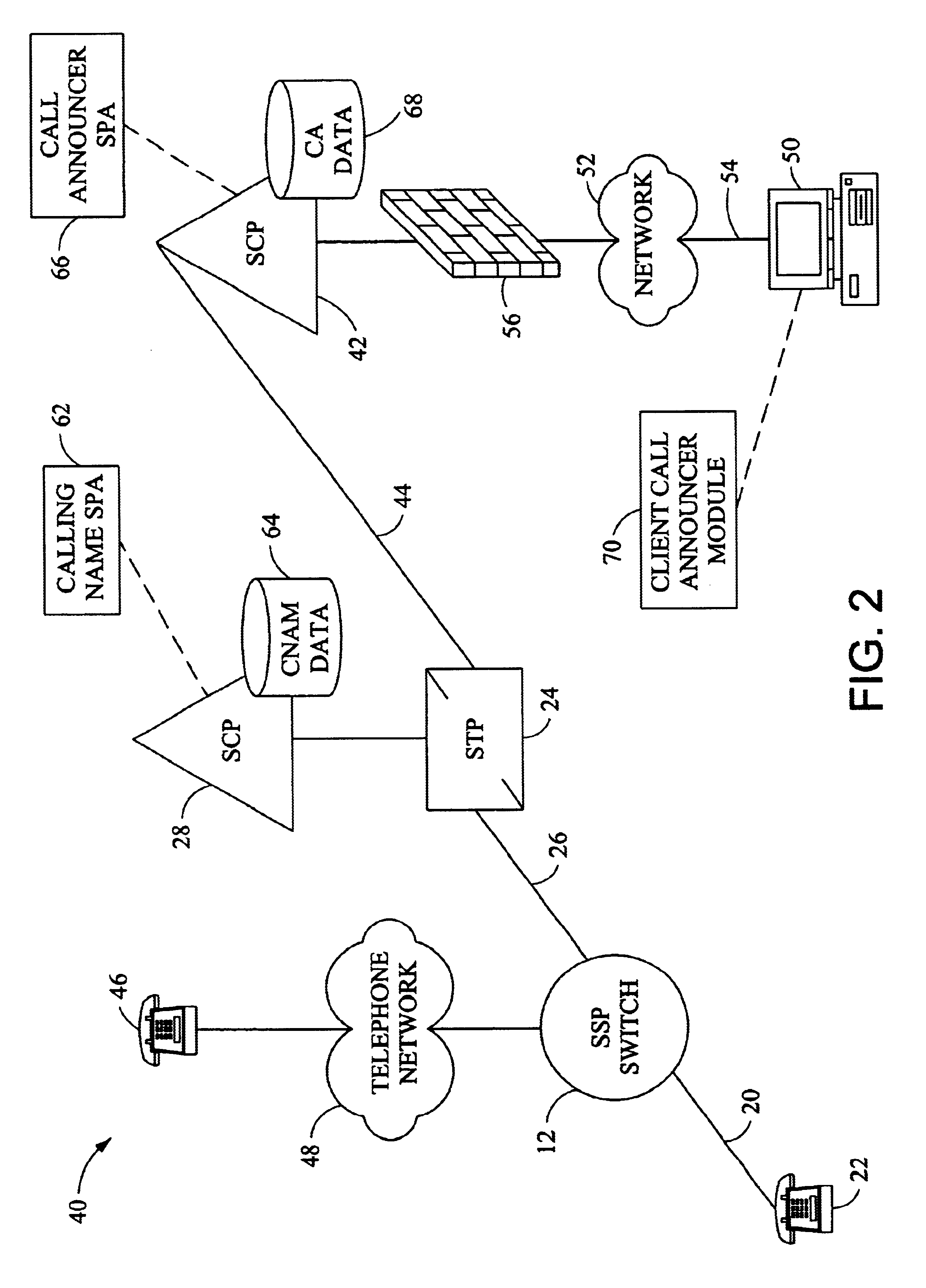
It is to be understood that the figures and descriptions of the present invention have been simplified to illustrate elements that are relevant for a clear understanding of the present invention, while eliminating, for purposes of clarity, other elements of a communications network. For example, certain operating system details and modules of certain of the intelligent platforms of the network are not described herein. Those of ordinary skill in the art will recognize, however, that these and other elements may be desirable in a typical communications network. However, because such elements are well known in the art, and because they do not facilitate a better understanding of the present invention, a discussion of such elements is not provided herein.

The term "calling party" is used herein generally to refer to the person or device that initiates a telecommunication. The calling party may also be referred to herein as "caller." In some cases, the calling party may not be a person, ...


PUM


Abstract

A system for monitoring incoming communications to a telecommunications device. The system includes a switch and a service control point in communication with each other. The switch is for detecting an incoming communication to the telecommunications device from a calling party, wherein the switch is in communication with the telecommunications device by a first communications link. The service control point is for receiving a first message from the switch regarding detection of the incoming communication and for sending a second message to a data communications device, the second message containing information regarding the calling party, wherein the service control point is in communications with the data communications device by a second communications link.

Description

Not Applicable.STATEMENT REGARDING FEDERALLY SPONSORED RESEARCH AND DEVELOPMENTNot Applicable.BACKGROUND OF INVENTION1. Field of InventionThe present invention relates generally to communications and, more particularly, to systems and methods for monitoring incoming communications to a telecommunications device.2. Description of the BackgroundDue to the proliferation of the Internet, the World Wide Web and user-friendly web browsers, millions of personal computer (PC) users have easy access to a great quantity of information and documents from around the world. Internet infrastructures are largely land-based, transmitting data over digital links and analog lines. Accordingly, all that is required for a typical PC user to connect to the Internet is a telephone line, a modem, and an Internet Service Provider (ISP), through which connection to the Internet is provided. Many, if not most, home PC users, however, have only one telephone line to their residential premises. Therefore, when...

Claims


Application Information

Patent Timeline
Patent Type & Authority Patents(United States)
IPC IPC(8): H04M3/42H04M1/57H04M3/64H04M7/00H04M3/60
CPCH04M3/4228H04Q3/0045H04M1/57H04Q2213/13389H04M3/42042H04M3/42068H04M3/64H04M7/006H04M2201/38H04M2242/22H04Q2213/13039H04Q2213/13091H04Q2213/13092H04Q2213/13093H04Q2213/13103H04Q2213/1315H04Q2213/13166H04Q2213/13175H04Q2213/13204H04Q2213/13298H04Q2213/13345H04M1/575
Inventor BEDINGFIELD, JAMES C.
Owner BELLSOUTH INTPROP COR
Why Eureka
Try Eureka