Gas turbine combustor

Inactive Publication Date: 2005-01-04
MITSUBISHI HITACHIPOWER SYST LTD
View PDF16 Cites 47 Cited by
  • Summary
  • Abstract
  • Description
  • Claims
  • Application Information

AI Technical Summary

Benefits of technology

According to the invention, a gas turbine combustor comprises a side wall for defining a combustion volume, having upstream and downstream ends, a pilot nozzle, disposed adjacent the upstream end of the side wall, for discharging a pilot fuel to form a diffusion flame in the combustion volume, and a plurality of main nozzles, provided around the pilot nozzles,

Problems solved by technology

In the conventional gas turbine combustor, the premixed flames complete the combustion process in a short length

Method used


Image

  • Gas turbine combustor
  • Gas turbine combustor
  • Gas turbine combustor

Examples


Embodiment Construction

With reference to the drawings, a preferred embodiment of the present invention will be described below.

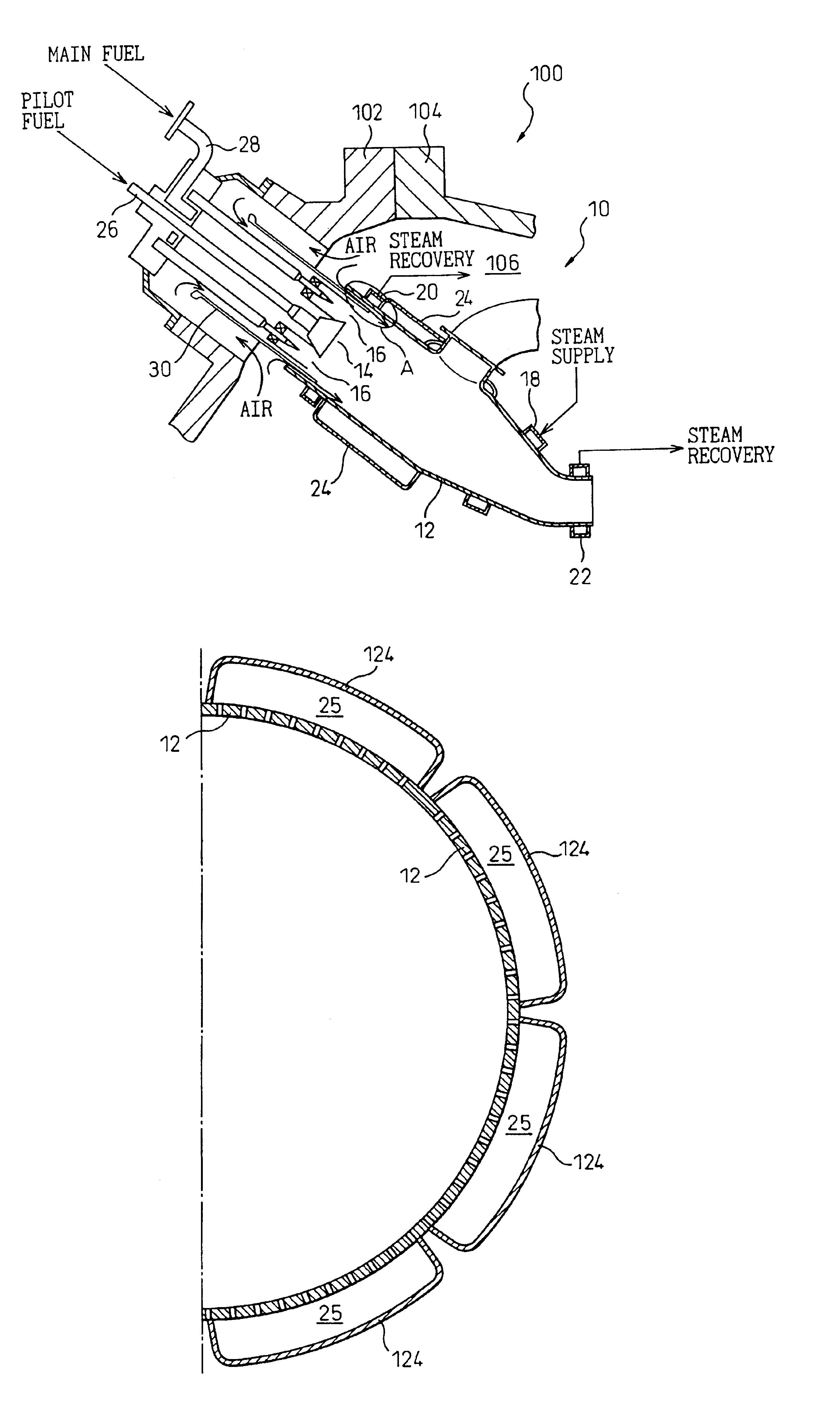
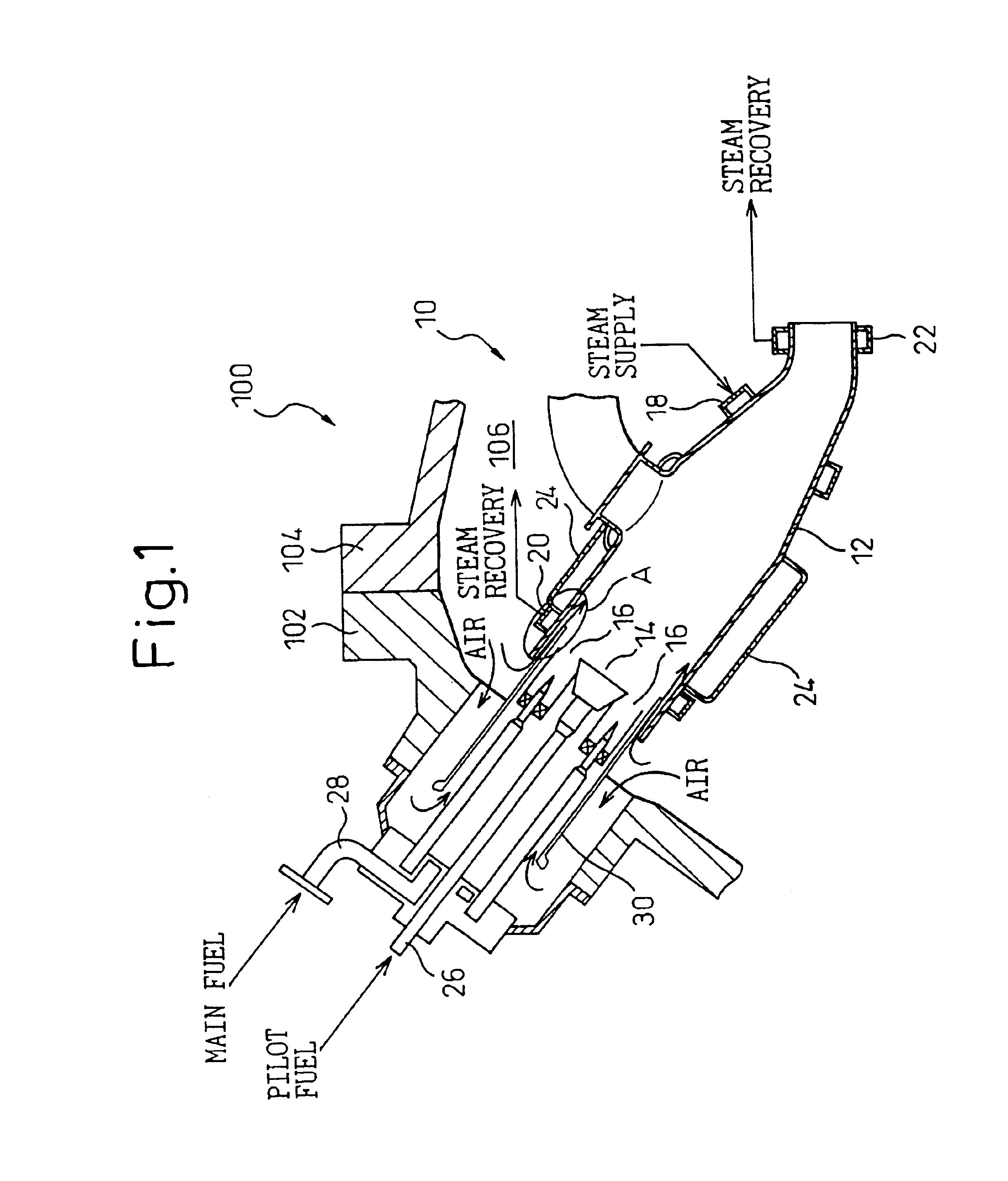
A gas turbine 100 according to the embodiment includes a compressor (not shown), an expander (not shown) connected to the compressor by a shaft, a casing 102 and 104 for enclosing the compressor and the expander, and a combustor 10 fixed to the casing 102 and 104. The air compressed by the compressor is supplied to the combustor 10 through a compressed air chamber 106 defined by the casing 102 and 104.

The combustor 10 has cylindrical a combustor tail tube 12 and an inner tube 30. A pilot nozzle 14 is provided at the center of the inner tube 30 around which a plurality of main nozzles 16 are disposed. A fuel, for example natural gas, is supplied as a pilot fuel to the pilot nozzle 14 through a pilot fuel supply conduit 26. The pilot nozzle 14 discharges the pilot fuel into the combustor tail tube 12 to form a diffusion flame. A fuel, for example natural gas, is supplied as a main f...


PUM


Abstract

A gas turbine combustor includes a side wall, for defining a combustion volume, having upstream and downstream ends, a pilot nozzle, disposed adjacent the upstream end of the side wall, for discharging a pilot fuel to form a diffusion flame in the combustion volume, and a plurality of main nozzles, provided around the pilot nozzles, for discharging a fuel-air mixture to form premixed flames in the combustion volume. Film air is supplied into the combustion volume downstream of the main nozzles along the inner surface of the side wall to reduce the fuel-air ratio in a region adjacent the inner surface of the side wall and to restrain a combustion-driven oscillation in the combustion volume.

Description

BACKGROUND OF THE INVENTION1. Field of the InventionThe invention relates to a gas turbine combustor.2. Description of the Related ArtConventional gas turbine utilizes a two-stage combustor which includes a pilot nozzle for forming a diffusion flame, as a pilot flame, along the axis of the combustor, and a plurality of main nozzles for discharging a fuel-air mixture to form premixed flames as the main combustion around the diffusion flame.In the conventional gas turbine combustor, the premixed flames complete the combustion process in a short length in the axial direction of the combustor which may result in short flames or a rapid combustion adjacent a wall. When the combustion process is completed within a small volume, the volumetric density of the energy released by the combustion or the combustion intensity in the combustor becomes high so that a combustion-driven oscillation can easily be generated within a plane perpendicular to the axis or in the peripheral direction. The co...

Claims


Application Information

Patent Timeline
IPC IPC(8): F23R3/06F23R3/04F23R3/00F23M13/00F02C7/18F23M20/00F23R3/10F23R3/30
CPCF23R3/005F23M20/005F23R3/06F23D2211/00F23R2900/00001F23R2900/00014
Inventor MANDAI, SHIGEMISUENAGA, KIYOSHIAOYAMA, KUNIAKIIKEDA, KAZUFUMITANAKA, KATSUNORI
Owner MITSUBISHI HITACHIPOWER SYST LTD
Why Eureka
Try Eureka