Combustion chamber with a closed cooling system for a turbine

a technology of closed cooling system and combustion chamber, which is applied in the direction of machines/engines, mechanical equipment, light and heating equipment, etc., to achieve the effect of reliable and low-resistance discharg

Inactive Publication Date: 2005-08-09
SIEMENS AG
View PDF7 Cites 19 Cited by
  • Summary
  • Abstract
  • Description
  • Claims
  • Application Information

AI Technical Summary

Benefits of technology

[0004]Given this prior art, the object of the invention is to improve a combustion chamber with a closed cooling system f

Problems solved by technology

The problem with this structure is that the tubes with a circular cross-section fed through the hollow tile block the flow path for the dis

Method used


Image

  • Combustion chamber with a closed cooling system for a turbine
  • Combustion chamber with a closed cooling system for a turbine
  • Combustion chamber with a closed cooling system for a turbine

Examples


first embodiment

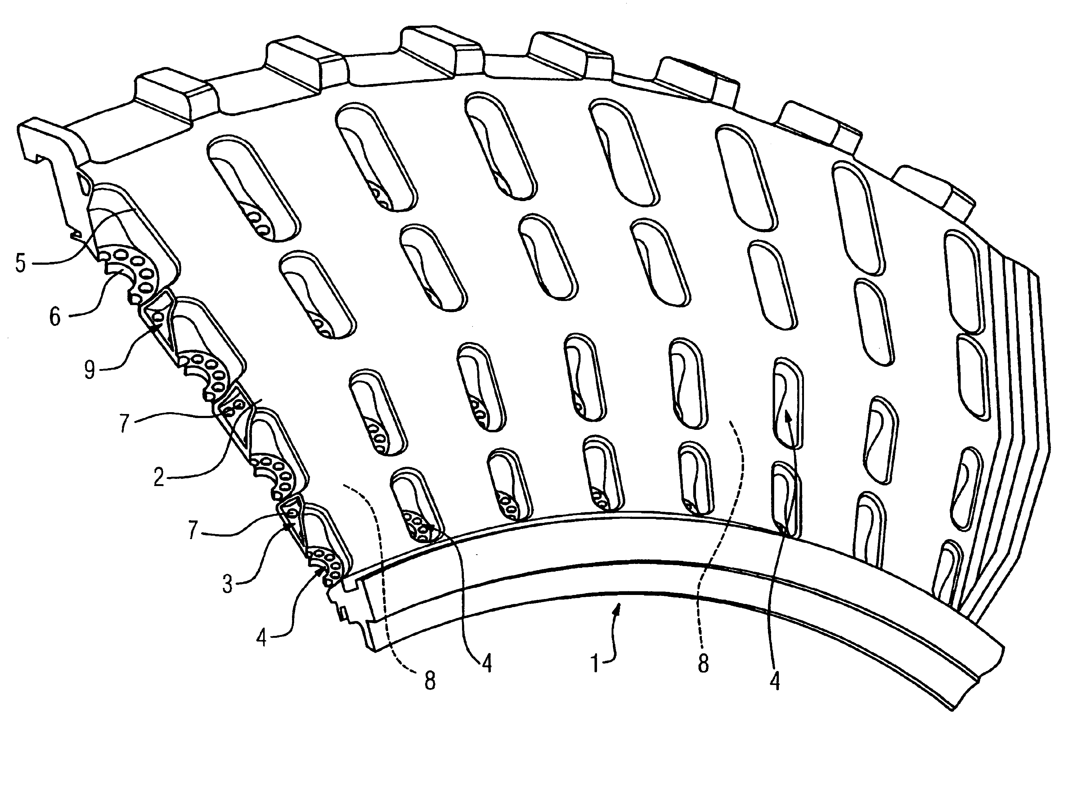
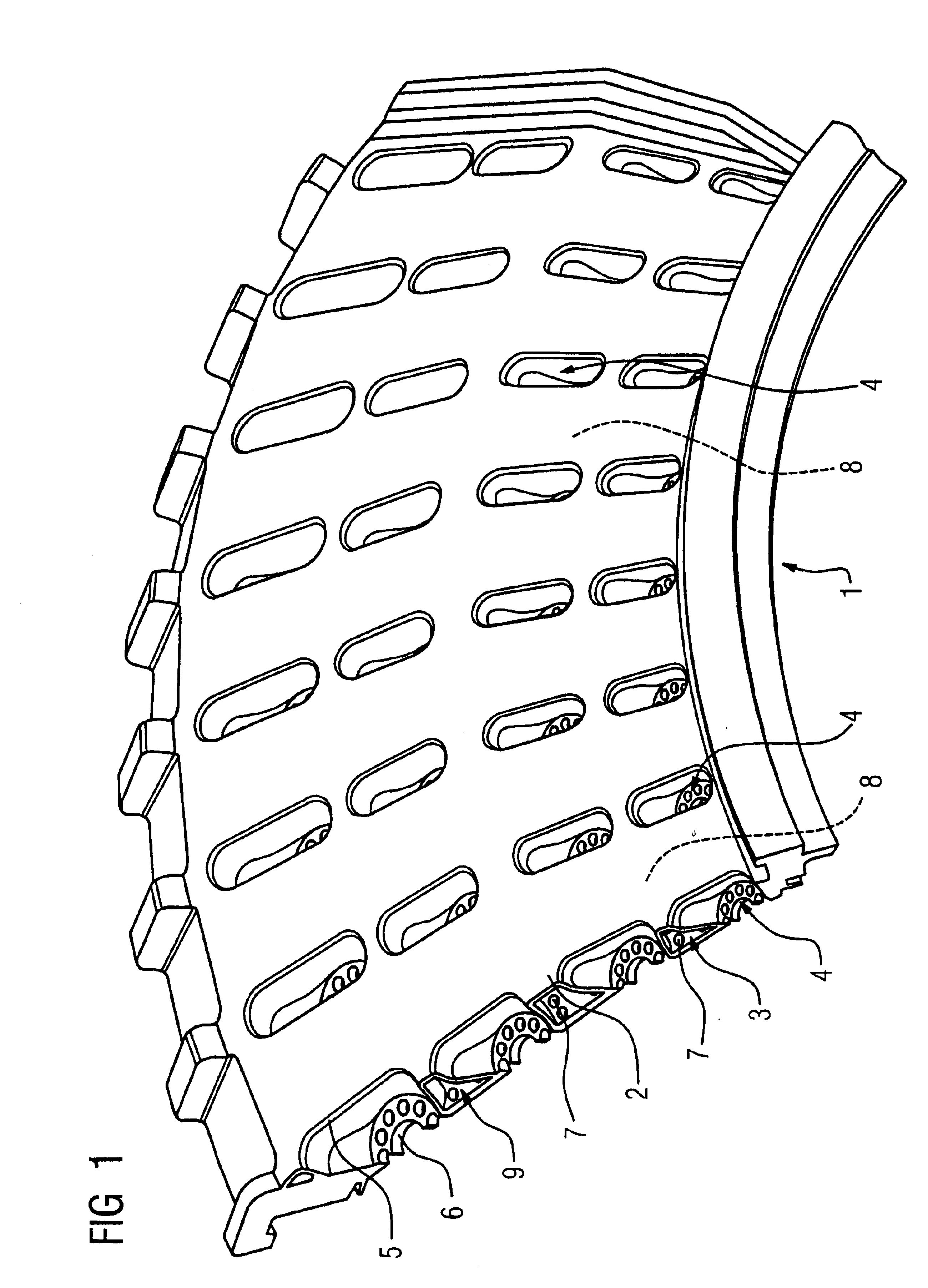
[0023]FIG. 1 shows an outer wall 1 of a combustion chamber according to the invention in a sectional, three-dimensional representation. The outer wall 1 is configured as a double-layer hollow tile. It comprises an outer layer 2 and an inner layer 3 facing towards the combustion chamber. Feed tubes 4 connect the outer layer 2 and the inner layer 3 together to feed in a cooling fluid. The feed tubes 4 have longitudinally extended oval openings 5 in the outer layer 2 and circular openings 6 in the inner layer 3. The feed tubes 4 here are arranged in rows one behind the other in the axial direction of the combustion chamber so that the narrow front faces of the longitudinally extended oval openings 5 abut each other firmly and there is a greater distance between the oval openings 5 of feed tubes 4 in adjacent rows than between the openings 5 in the rows. This means that channel-type drainage structures 8 running in the axial direction of the combustion chamber are created between the ro...

second embodiment

[0026]FIGS. 3 and 4 show the invention. The outer wall 1 shown here is not configured as a hollow tile but comprises a single-layer wall 20, which comprises ribs 21 running in the axial direction of the combustion chamber. Covers 22 are placed on the ribs 21 and welded to the ribs to form drainage channels. The drainage channels thus formed open out into drainage openings 23, through which the discharged fluid exits. In the area between the ribs 21, on which the cover 22 rests, openings 7 open out to discharge cooling fluid. The area between the ribs 21, which is not covered by covers 22 to form drainage channels, contains circular openings 6 to feed in cooling fluid. In order to feed in the cooling fluid as comprehensively as possible and with even distribution, while keeping the drainage channels large enough, the ribs 21 are curved into a wave shape at their base in order to facilitate the transition to the circular openings 6. In this way cooling fluid entering between the drain...


PUM


Abstract

In order to develop a combustion chamber with a closed cooling system for a turbine with an inner wall and an outer wall (1) bounding the combustion area, wherein there is an intermediate space between the inner wall and the outer wall (1) through which cooling fluid can flow, and which comprises a cooling fluid feed system opening out into the intermediate space and a cooling fluid discharge system for discharging the cooling fluid from the intermediate space, so that it has a reduced extension in the radial direction, it is proposed with the invention that the cooling fluid discharge system should comprise channel-type drainage structures (8) running essentially along the axial orientation of the combustion chamber, which are interrupted by inlet structures (4) of the cooling fluid feed system arranged between the drainage structures (8).

Description

CROSS REFERENCE TO RELATED APPLICATIONS[0001]This application claims priority to the European application No. 02028486.5 EP, filed Dec. 19, 2002 under the European Patent Convention and which is incorporated by reference herein in its entirety.FIELD OF INVENTION[0002]The invention relates to a combustion chamber with a closed cooling system for a turbine.BACKGROUND OF INVENTION[0003]Combustion chambers of this type are enclosed by a double wall comprising an inner wall and an outer wall, whereby there is an intermediate space between the inner wall and the outer wall, through which a cooling fluid, generally cooling air, can flow. To cool the combustion chamber, a cooling fluid, generally cooling air, is fed into the intermediate space through a cooling fluid feed system opening out into the intermediate space, and the cooling fluid leaves the intermediate space via a cooling fluid discharge system after absorbing the heat to be discharged from the combustion chamber. With known com...

Claims


Application Information

Patent Timeline
IPC IPC(8): F23R3/00F23M7/04F23M7/00F02C7/18F02C7/28F23R3/42
CPCF23M7/04F23R3/005F23R2900/03044
Inventor TIEMANN, PETER
Owner SIEMENS AG
Why Eureka
Try Eureka