Acoustic wave bandpass filter comprising integrated acoustic guiding

a bandpass filter and integrated technology, applied in the direction of impedence networks, electric devices, etc., can solve the problems of reducing the transmission efficiency of filters, reducing the efficiency of filters, and allowing all desired conversion ratios to be obtained, so as to achieve better channeling of waves, avoid technological complexity of crf filters, and widen the range of impedance ratios

Active Publication Date: 2016-09-20
COMMISSARIAT A LENERGIE ATOMIQUE ET AUX ENERGIES ALTERNATIVES
View PDF11 Cites 14 Cited by
  • Summary
  • Abstract
  • Description
  • Claims
  • Application Information

AI Technical Summary

Benefits of technology

[0012]In this context, the subject of the present invention is a solution allowing impedance conversion and / or mode conversion to be achieved using acoustically coupled resonators. This conversion is obtained while electrical isolation between the input and the output of the filter is ensured, the isolation itself being obtained via the propagation of acoustic waves between the resonators of the filter. According to the invention, the guiding of said waves allows better channeling of the waves to be achieved, and therefore resonators with different geometries to be used. The conversion according to the invention also allows the technological complexity of a CRF filter to be avoided, while making it possible to achieve a wider range of impedance ratios and limiting the risk of internal electrical reflections in the case of high order filters.
[0017]The first and / or second phononic crystal structures make it possible to converge or diverge (and therefore guide) the acoustic waves from one surface toward the other, depending on their respective dimensions.

Problems solved by technology

Baluns are systems which take up a lot of space and introduce losses.
This solution raises the same manufacturing problems as the CRFs, namely requiring numerous layers to be stacked and numerous mask levels to be used.
In addition, the thicknesses are fixed within certain limits by acoustic constraints (the desired frequencies, the bandwidth, the coupling coefficients of the modes used, etc.), not allowing all the desired conversion ratios to be obtained.
For this reason, electrical reflections are created inside the filter, which reflections degrade the transmission of the filter, and thus its performance.

Method used


Image

  • Acoustic wave bandpass filter comprising integrated acoustic guiding
  • Acoustic wave bandpass filter comprising integrated acoustic guiding
  • Acoustic wave bandpass filter comprising integrated acoustic guiding

Examples


first embodiment

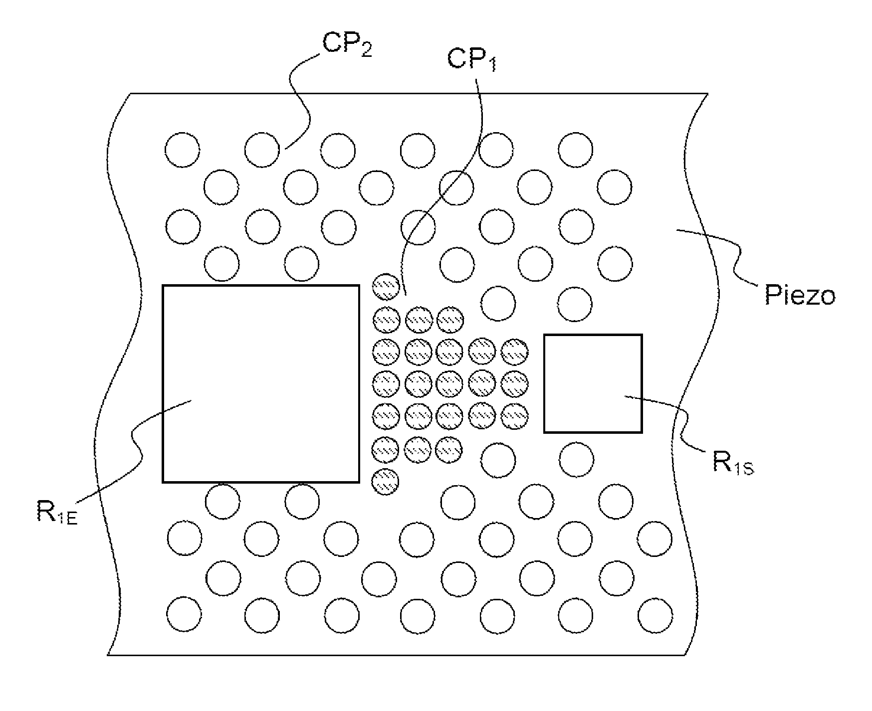
[0057]According to the invention, a phononic crystal is placed coupling the resonators together, and waves are guided using another phononic crystal designed to reflect almost all of the waves and thus confine the latter in or between the resonators, as illustrated in FIG. 5. Typically, the input resonator R1E and the output resonator R1S do not have the same dimensions and therefore the same impedances (which are dependent on their dimensions). A first phononic crystal structure CP1 is incorporated between said resonators R1E and R1S, in the layer of piezolectric material Piezo. A second phononic crystal structure CP2 is provided at the periphery of the input and output resonators, so as to confine the acoustic waves, this second structure ensuring a mirror effect with respect to the acoustic waves. The crystal CP1 should have a transmission coefficient set by the desired bandwidth, and the phononic crystal CP2 should have the highest possible reflection coefficient.

second embodiment

[0058]According to the invention, it is possible to configure the first phononic crystal structure so as to provide it with a lens function with respect to the acoustic waves, such a lens structure is shown in FIG. 6, which illustrates a configuration for such a CP1L structure produced in the layer of piezolelectric material Piezo, which no longer requires a guiding structure on either side of the two input and output resonators; such lens-effect phononic crystal configurations are notably described in the following articles: A. C. Hladky-Hennion, J. Vasseur, B. Dubus, B. Djafari-Rouhani, D. Ekeom and B. Morvan, Numerical analysis of negative refraction of transverse waves in an elastic material, Journal of Applied Physics, 104, n° 064906, 2008, M. H. Lu, L. Feng and Y. F. Chen, Phononic crystals and acoustic metamaterials, Materials Today, 12, 12, pp. 34-42, 2009.

third embodiment

[0059]According to the invention, the filter may advantageously comprise coupled resonators. The addition of supplementary resonators improves the selectivity of the filter. FIG. 7 illustrates in this regard a configuration comprising two first resonators R1E and R2E, and two second resonators R1S and R2S, each resonator being separated from an adjacent resonator by a phononic crystal structure: a first conversion structure CP1 between the two resonators R1E and R1S, and a second guiding phononic crystal structure CP2 and third phononic crystal structures CP3 for improving the selectivity of the filter.

[0060]The present invention makes it possible to envision simultaneous impedance and mode conversion since it is possible to guide the waves toward two resonators rather that to only one. Depending upon the technology used, it is also possible to electrically connect the two output resonators, either directly or via an inverter, as shown more specifically in FIG. 8, which shows the po...


PUM


Abstract

An acoustic wave bandpass filter comprises at least an input first acoustic wave resonator with an output surface, and an output second acoustic wave resonator with an input surface, said resonators being coupled to each other along a set direction, the input and output surfaces being substantially opposite, and at least one first phononic crystal structure between said input and output resonators and / or a second phonic crystal structure at the periphery of said resonators so as to guide the acoustic waves, generated by said input resonator, toward said output resonator along said set direction, the resonators ensuring an impedance conversion and / or a mode conversion.

Description

CROSS-REFERENCE TO RELATED APPLICATIONS[0001]This application is a National Stage of International patent application PCT / EP2011 / 067728, filed on Oct. 11, 2011, which claims priority to foreign French patent application No. FR 1058404, filed on Oct. 15, 2010, the disclosures of which are incorporated by reference in their entirety.FIELD OF THE INVENTION[0002]The field of the invention is that of electromechanical devices using acoustic wave propagation through piezoelectric or electrostrictive layers to create electrical filter functions and, in addition, ensure electrical isolation between the input and output of the component.BACKGROUND[0003]Such devices have operating frequencies of the order of a few hundred MHz to a few GHz, and are used in radiofrequency transmission circuits (mobile phone, radio link, wireless exchange of data, etc.) signal processing or in sensor systems.[0004]More specifically, the field of the present invention relates to electrical isolation, the input an...

Claims


Application Information

Patent Timeline
Patent Type & Authority Patents(United States)
IPC IPC(8): H03H9/64H03H9/02H03H9/56H03H9/54H03H9/00
CPCH03H9/6433H03H9/02015H03H9/02047H03H9/02086H03H9/02543H03H9/02653H03H9/02818H03H9/547H03H9/564H03H9/0033H03H9/0095H03H9/6436H03H9/6453
Inventor GORISSE, MARIEREINHARDT, ALEXANDRE
Owner COMMISSARIAT A LENERGIE ATOMIQUE ET AUX ENERGIES ALTERNATIVES
Why Eureka
Try Eureka