PON transmission system and dynamic band assignment system to be employed in the same

a transmission system and dynamic band technology, applied in data switching networks, multiplex communication, star/tree networks, etc., can solve the problems of complex processing and the inability of conventional pon transmission systems to assign the band at high speed, and achieve the effect of effectively using up the band in the pds section and high speed

Inactive Publication Date: 2005-08-16
NEC CORP
View PDF11 Cites 19 Cited by
  • Summary
  • Abstract
  • Description
  • Claims
  • Application Information

AI Technical Summary

Benefits of technology

[0019]The present invention has been worked out in view of the problem set forth above. It is therefore an object of the present invention to provide a PON transmission system and a dynamic band assignment system to be employed in the same which permits high speed band variation, to effectively use up band in PDS section, and to adapt to variation of traffic type.

Problems solved by technology

In the conventional PON transmission system, when attempt is made to process a traffic required band restriction and a traffic unnecessary for band restriction in a single grant, high precision band assignment is necessary for the traffic which does not require band restriction equivalent to that for the traffic requiring the band restriction, and the process is complicate unless the band updating speed is adapted to a period of the traffic requiring band restriction.
Therefore, the conventional PON transmission system cannot assign the band at high speed.

Method used


Image

  • PON transmission system and dynamic band assignment system to be employed in the same
  • PON transmission system and dynamic band assignment system to be employed in the same
  • PON transmission system and dynamic band assignment system to be employed in the same

Examples


Embodiment Construction

[0069]The present invention will be discussed hereinafter in detail in terms of the preferred embodiment of the present invention with reference to the accompanying drawings. In the following description, numerous specific details are set forth in order to provide a thorough understanding of the present invention. It will be obvious, however, to those skilled in the art that the present invention may be practiced without these specific details.

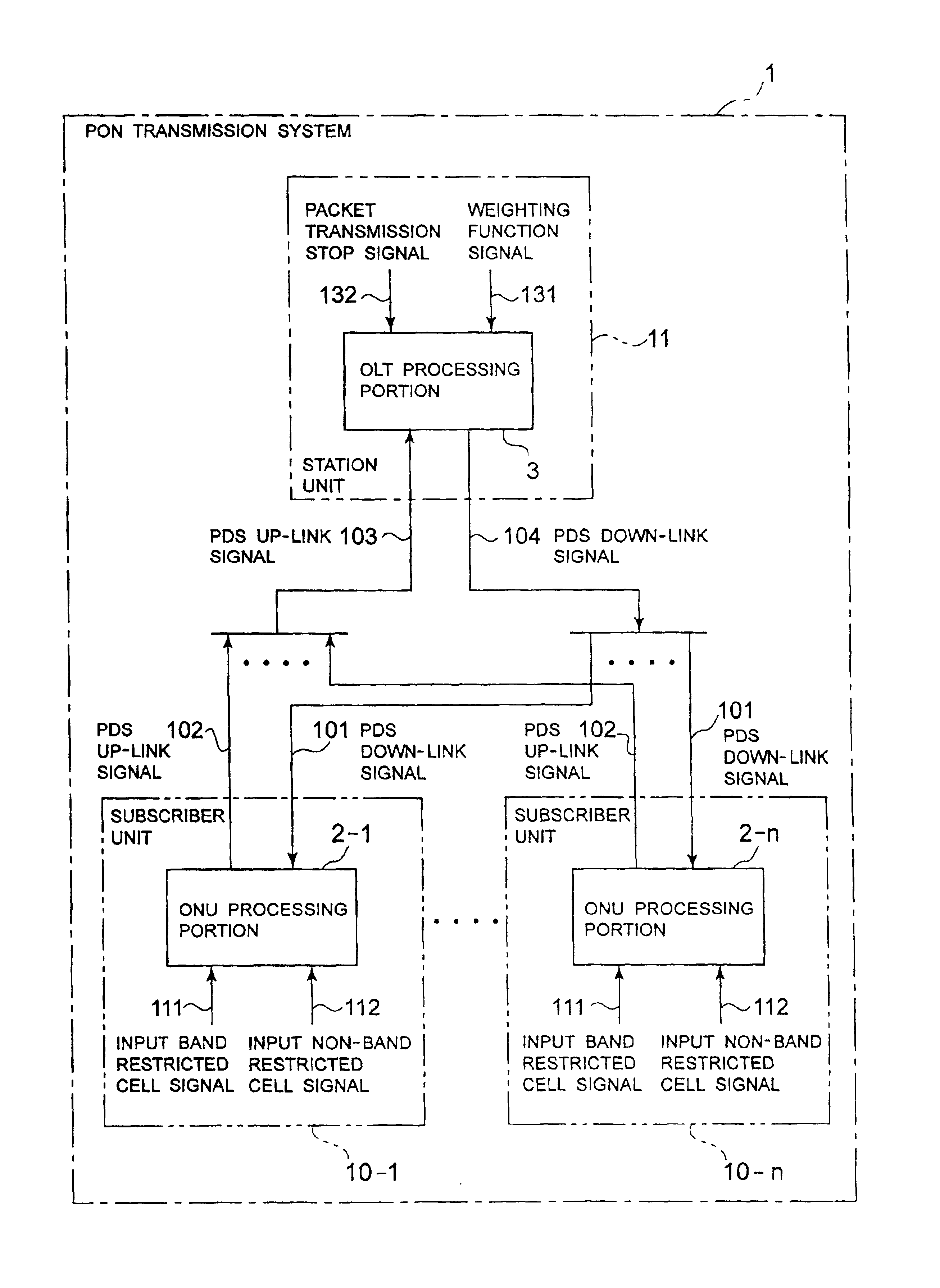
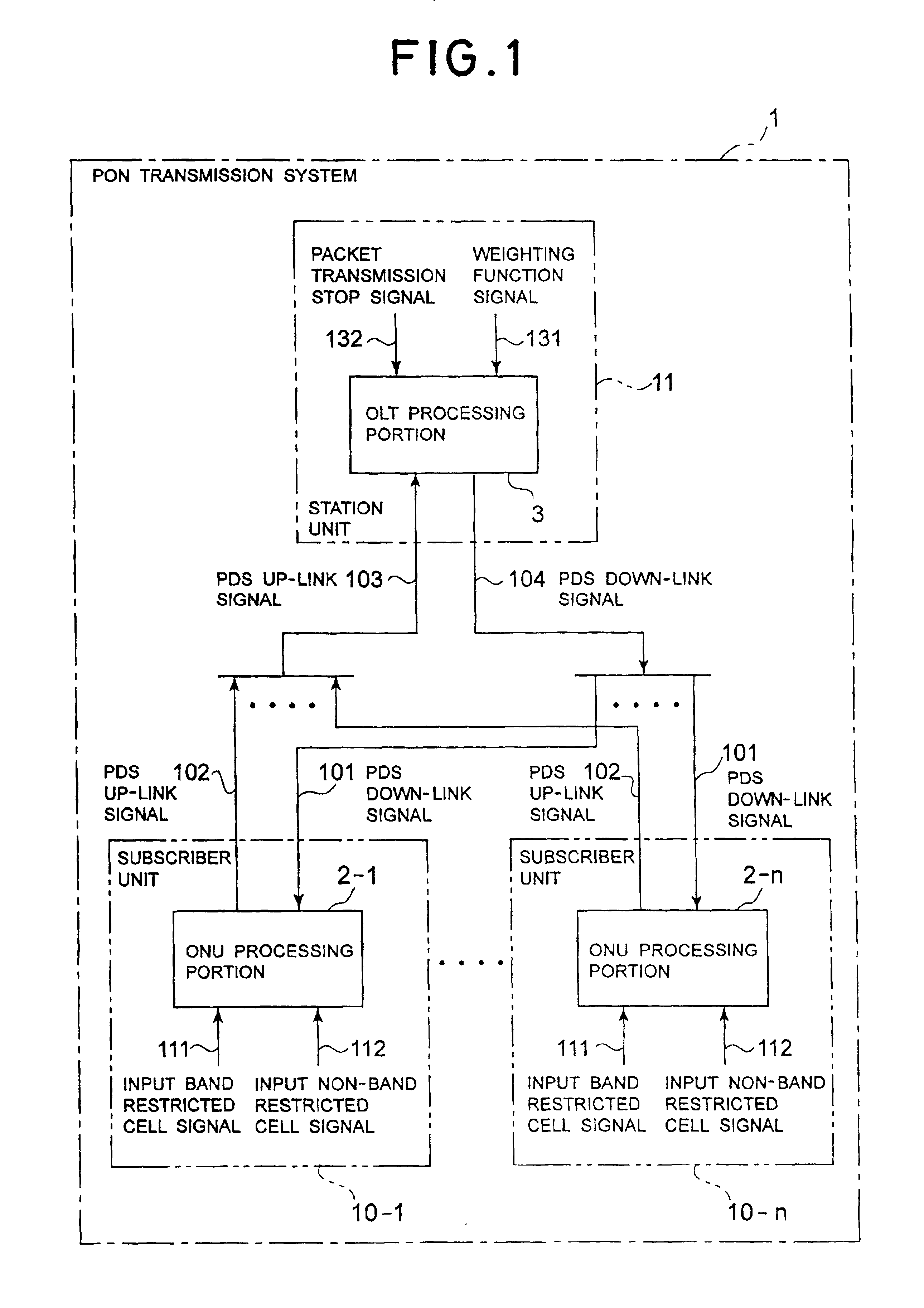
[0070]FIG. 1 is a block diagram showing a construction of one embodiment of a passive optical network (PON) transmission system according to the present invention. In FIG. 1, the PON transmission system 1 is constructed with optical network unit processing portions 2-1 to 2-n terminating an optical communication network on the side of subscriber units 10-1 to 10-n, and an optical line terminal (OLT) processing portion 3 terminating the optical communication network on the side of station equipment 11.

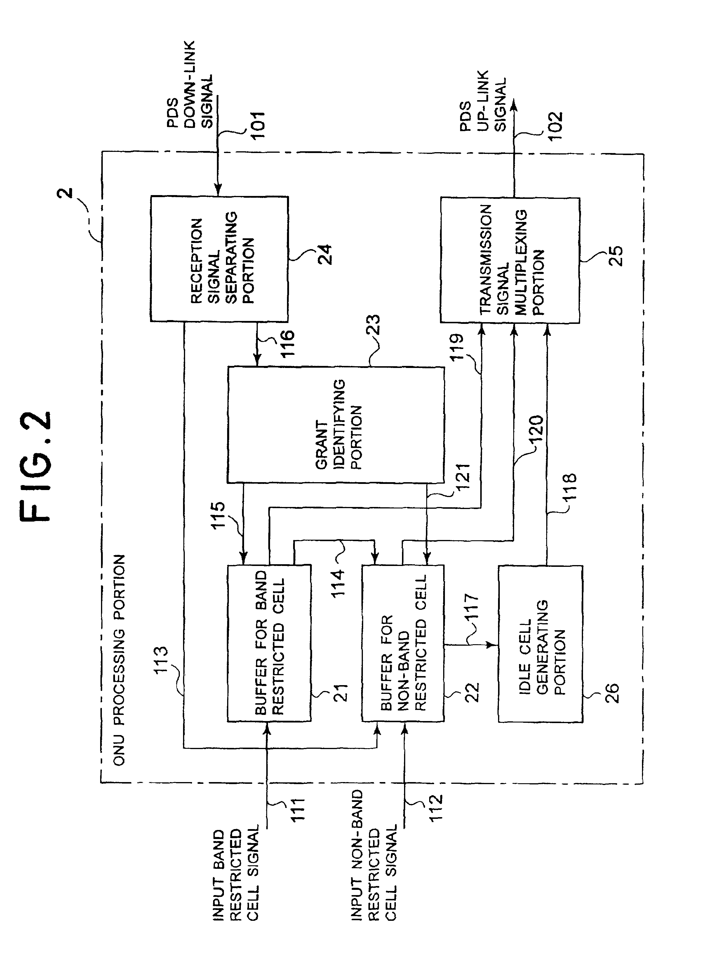
[0071]FIG. 2 is a block diagram showing a c...


PUM


Abstract

A PON transmission system and a dynamic band assignment system to be employed in the same which permits high speed band variation, to effectively use up band in PDS period, and to adapt to variation of traffic type. The PON transmission system includes a plurality of subscriber unit including optical network unit processing portions for terminating an optical communication network and a station unit including optical line terminal processing portion terminating the optical communication network. The system also includes means for monitoring increasing and decreasing of idle cells, means for recognizing accumulation of cell in the optical network unit processing portion depending upon the result of monitoring, and means for individually handling band process in the optical communication network according to necessary or unnecessary of band restriction depending upon traffic type.

Description

BACKGROUND OF THE INVENTION[0001]1. Field of the Invention[0002]The present invention relates to a passive optical network (PON) transmission system and a dynamic band assignment system to be employed in the same. More particularly, the invention relates to a dynamic band assignment system in the PON transmission system.[0003]2. Description of the Related Art[0004]Conventionally, a PON transmission system includes an optical network unit (ONU) processing portion for terminating on the side of a subscriber unit and an optical line terminal (OLT) processing portion terminating on the side of station equipment in an optical network.[0005]As shown in FIG. 25, the ONU processing portion 6 is constructed with a buffer 61 for band restricted cell, a buffer 62 for non-band restricted cell, a grant identifying portion 63, a reception signal separating portion 64, a transmission signal multiplying portion 65, an idle cell generating portion 66 and a short cell generating portion 67.[0006]The ...

Claims


Application Information

Patent Timeline
Patent Type & Authority Patents(United States)
IPC IPC(8): H04J3/16H04Q11/00H04B10/556H04B10/07H04B10/272H04B10/524H04L12/44H04L12/911
CPCH04J3/1682H04J3/1694H04Q11/0062H04Q11/0067H04Q11/0071H04Q2011/0064H04Q2011/0081H04Q2011/0083
Inventor SAIKUSA, NAOKI
Owner NEC CORP
Why Eureka
Try Eureka