Line coupling structure, mixer, and receiving/transmitting apparatus comprised of suspended line and dielectric waveguide

a dielectric waveguide and line coupling technology, which is applied in the direction of waveguides, modulation transference by distributed inductance and capacitance, electrical devices, etc., can solve the problems of difficult mounting, difficult to fix circuit boards, and various problems disclosed in the above-described document, and achieve the effect of reducing transmission loss

Inactive Publication Date: 2005-08-16
MURATA MFG CO LTD
View PDF8 Cites 5 Cited by
  • Summary
  • Abstract
  • Description
  • Claims
  • Application Information

AI Technical Summary

Benefits of technology

[0010]In order to overcome the problems described above, preferred embodiments of the present invention provide a line coupling structure that has lower transmission loss between a dielectric waveguide and a suspended line, a mixer including such a line coupling structure, and a receiving / transmitting apparatus including such a mixer.

Problems solved by technology

However, the structure disclosed in the above-described document has various problems.
Specifically, since the circuit board carrying the diode is arranged in a direction that is perpendicular to the lengthwise direction of the dielectric strips, it is difficult to have the circuit board be fixed and it tends to tilt, which makes it difficult to mount.
Insertion of a sheet having a high dielectric constant into the NRD waveguide, providing a gap therein, or other measures are required to achieve matching in the structure, and therefore, the above-described structure cannot be easily designed and fabricated.
In a coupler including the NRD waveguide, the greater the difference from the frequency at which the power distribution ratio is even, the higher the possibility that the power distribution ratio lacks balance.

Method used


Image

  • Line coupling structure, mixer, and receiving/transmitting apparatus comprised of suspended line and dielectric waveguide
  • Line coupling structure, mixer, and receiving/transmitting apparatus comprised of suspended line and dielectric waveguide
  • Line coupling structure, mixer, and receiving/transmitting apparatus comprised of suspended line and dielectric waveguide

Examples


Embodiment Construction

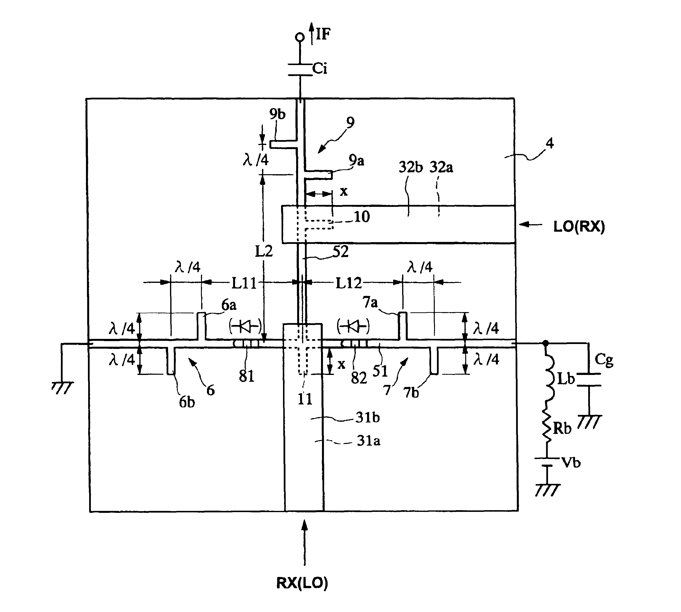
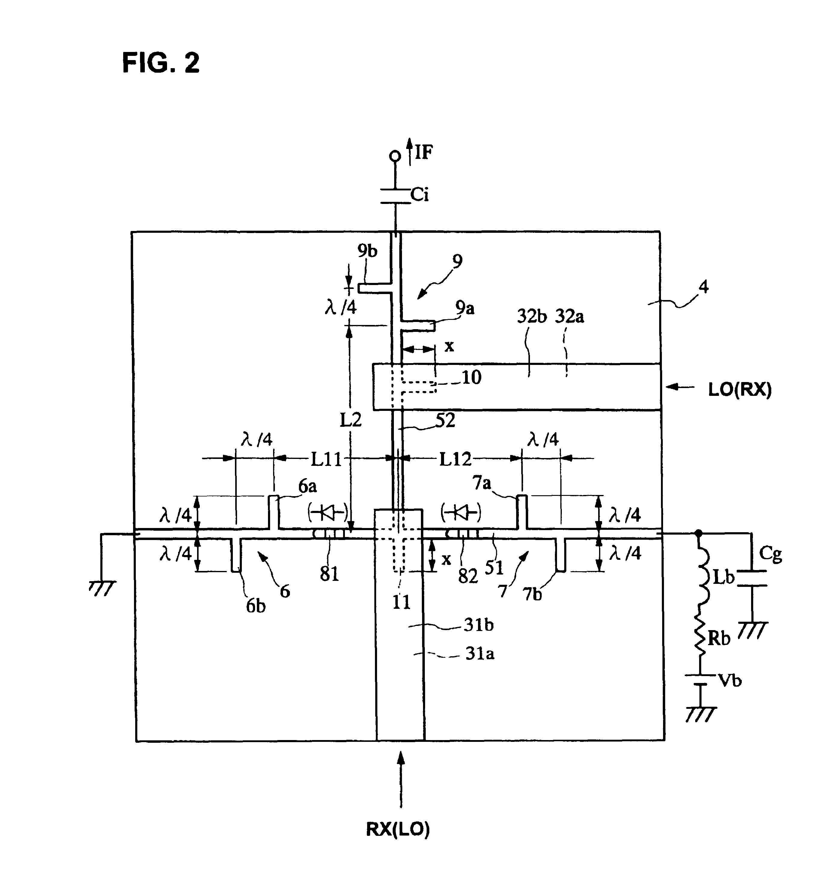
[0024]The structure of a balanced mixer according to preferred embodiments of the present invention will now be described with reference to FIGS. 1 to 5.

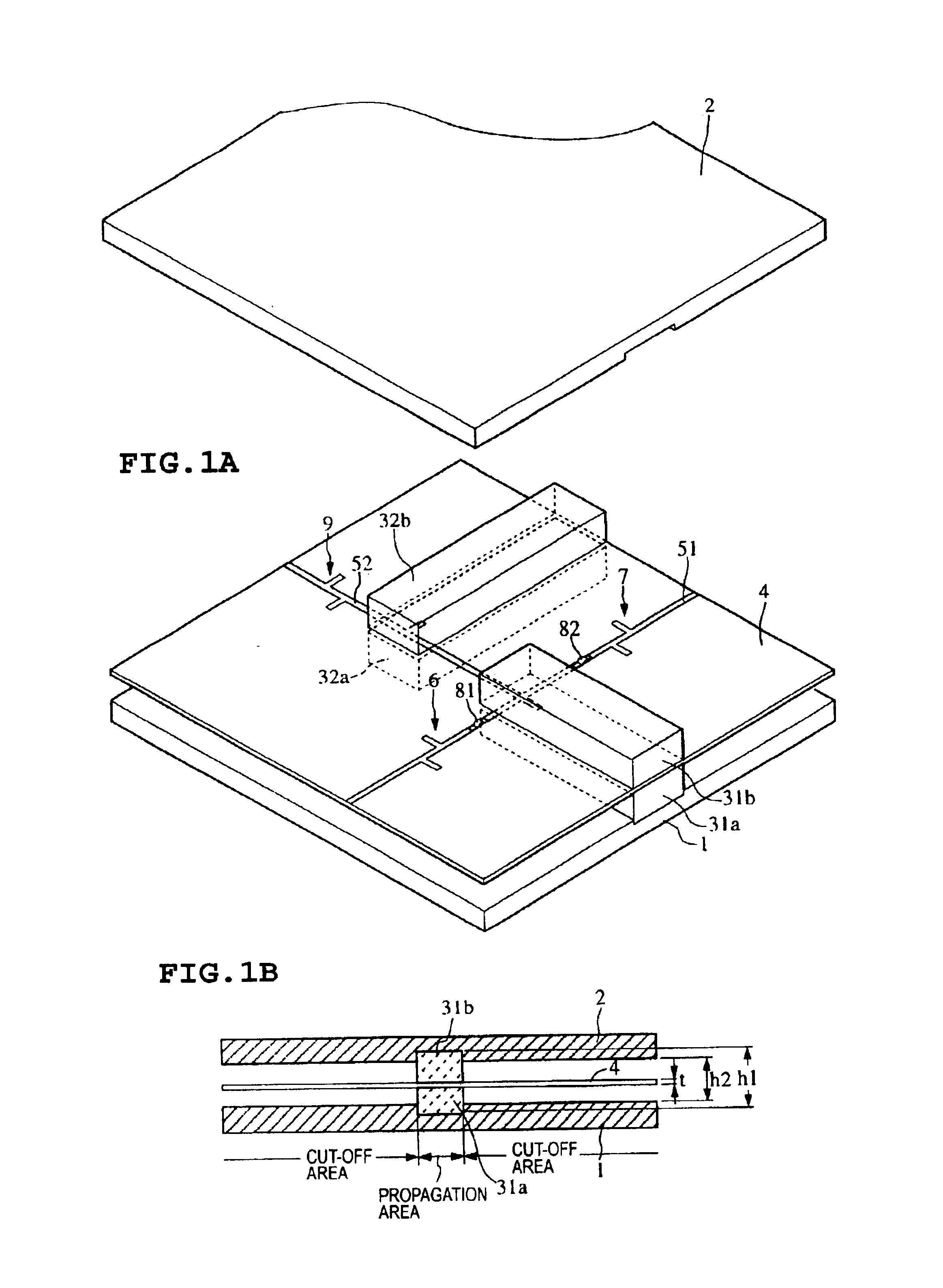
[0025]FIG. 1A is an exploded perspective view showing the structure of a balanced mixer according to a preferred embodiment of the present invention when an upper conductor plate 2 is raised. FIG. 1B is a sectional view showing the structure of the balanced mixer according to this preferred embodiment. Referring to FIGS. 1A and 1B, a lower conductor plate 1 and the upper conductor plate 2 constitute two conductor planes arranged substantially parallel to each other one above the other. First dielectric strips 31a and 31b and second dielectric strips 32a and 32b (see FIG. 1A) are vertically sandwiched between the two conductor plates 1 and 2. A circuit board 4 is sandwiched between the first dielectric strips 31a and 31b and between the second dielectric strips 32a and 32b. The conductor plates 1 and 2 have corresponding grooves into...


PUM


Abstract

A line coupling structure for coupling a dielectric waveguide to a suspended line has the dielectric waveguide including dielectric strips and two conductor plates that are approximately parallel to each other, the dielectric strips and a circuit board being sandwiched between the conductor plates. The line coupling structure also has the suspended line including the conductor plates and a conductor pattern on the circuit board. The conductor pattern is arranged in a direction that is substantially perpendicular to the dielectric strips. A protruding conductor pattern that extends in the extending direction of the dielectric strips is provided at a crossing position of the conductor pattern and the dielectric strips.

Description

BACKGROUND OF THE INVENTION[0001]1. Field of the Invention[0002]The present invention relates to a line coupling structure for coupling a dielectric waveguide, in which signals such as millimeter waves propagate, to a suspended line. The present invention also relates to a mixer including such a line coupling structure and further relates to a receiving / transmitting apparatus including such a mixer.[0003]2. Description of the Related Art[0004]A diode mounting structure in a nonradiative dielectric waveguide (hereinafter referred to as an NRD waveguide) and a mixer with such a structure are disclosed in Kuroki and Yoneyama “Circuit Elements In Nonradiative Dielectric Waveguide Using Beam Lead Diodes”, Journal of IEICE (The Institute of Electronics, Information and Communication Engineers), C-I, Vol J-73-C-I, No. 2, pp. 71-76 (February 1989).[0005]This mixer has a structure in which a coupler includes an NRD waveguide, and a circuit board carrying a diode is vertically sandwiched betw...

Claims


Application Information

Patent Timeline
Patent Type & Authority Patents(United States)
IPC IPC(8): H01P5/16H01P5/18H01P5/10H01P1/00H01P3/16H01P5/02H01P5/08H03D9/06H04B1/40
CPCH01P5/1022H01P5/18H01P5/02
Inventor IWATANI, HIDETOSHIYAMASHITA, SADAO
Owner MURATA MFG CO LTD
Why Eureka
Try Eureka