Replacement mitral valve

a technology of mitral valve and replacement valve, which is applied in the field of replacement valves for the circulatory system, can solve the problems that the papillary muscle no longer provides this assistance function, and achieve the effect of facilitating installation and mimicing the human mitral valv

Inactive Publication Date: 2005-09-20
SEDRANSK KYRA L
View PDF15 Cites 154 Cited by
  • Summary
  • Abstract
  • Description
  • Claims
  • Application Information

AI Technical Summary

Benefits of technology

[0011]One advantage of the present invention is that it mimics the human mitral valve more accurately.
[0012]Another advantage of the present invention resides in its ease of installation using conventional surgical tec

Problems solved by technology

After a valve replacement with any of the above-discussed replacement v

Method used


Image

  • Replacement mitral valve
  • Replacement mitral valve
  • Replacement mitral valve

Examples


Embodiment Construction

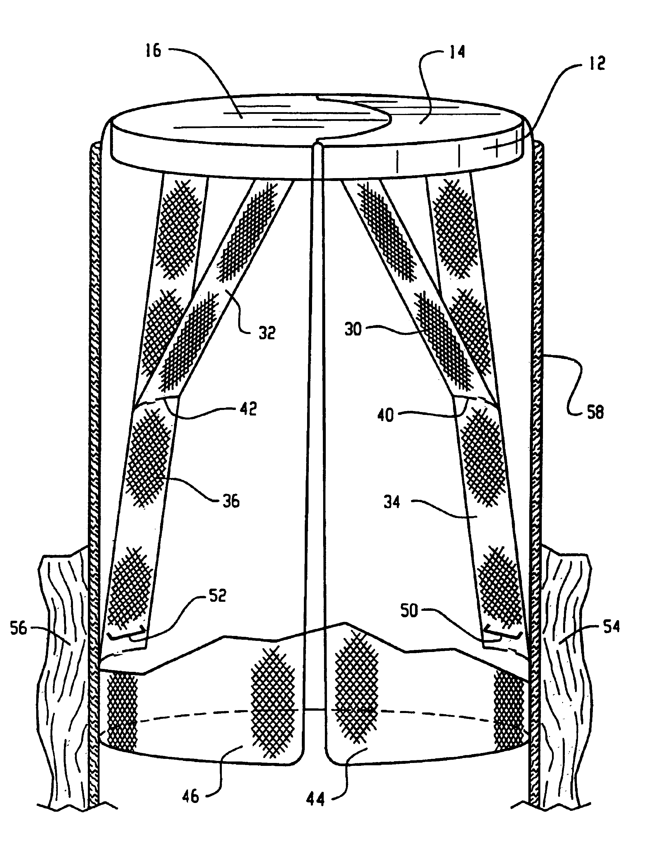
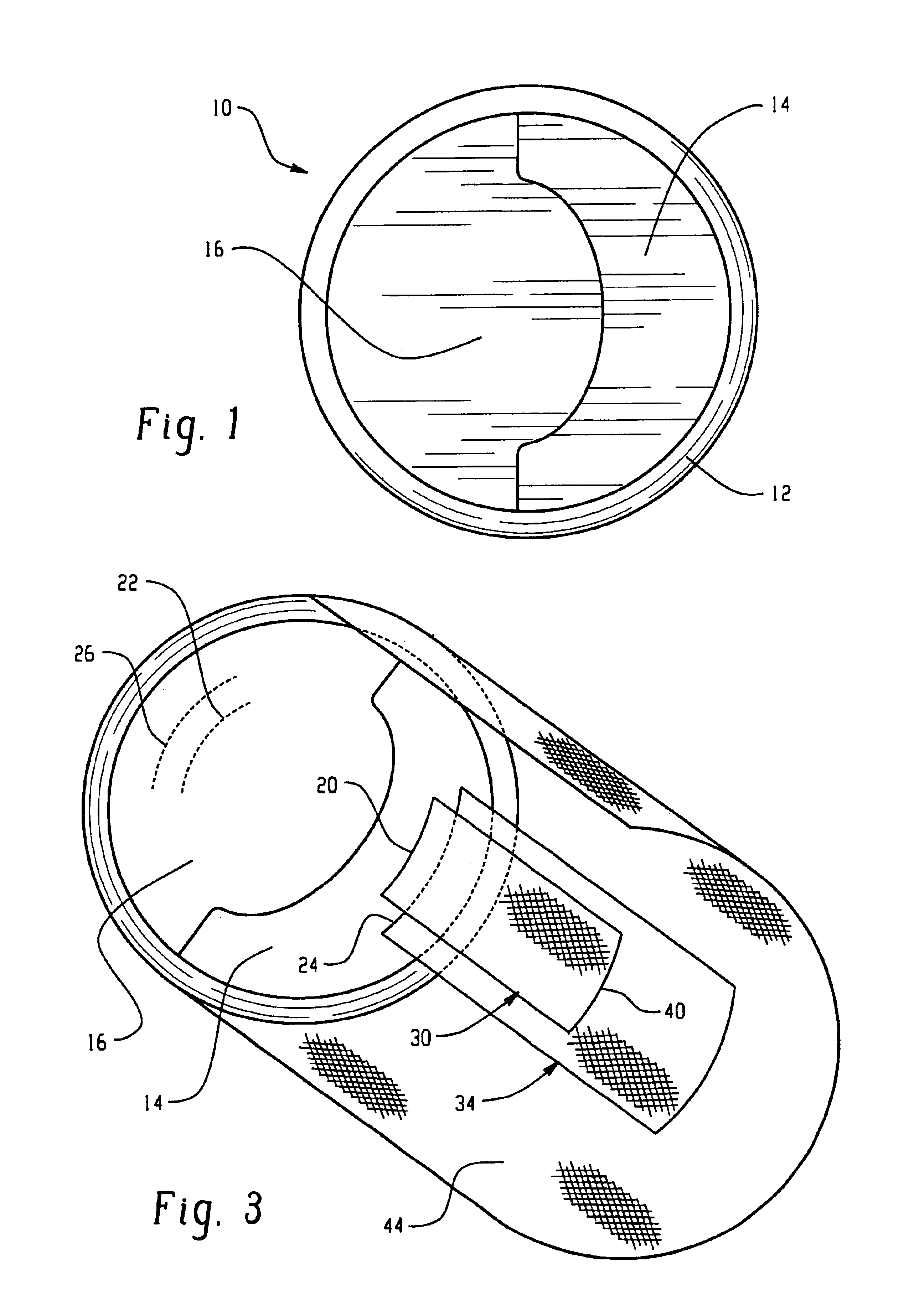
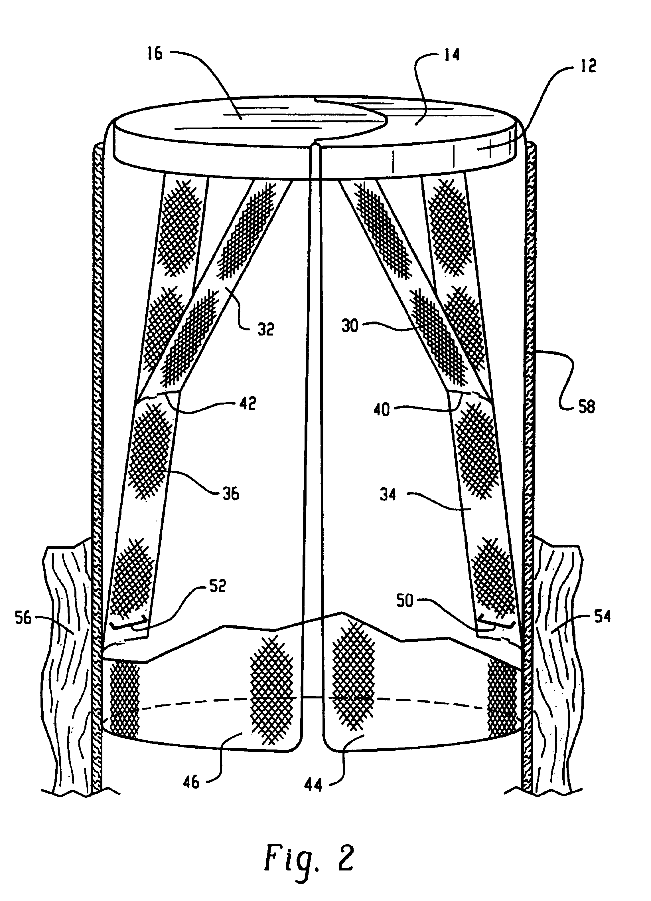
[0019]With reference to FIG. 1, a replacement mitral valve 10 includes a sewing ring 12 around its periphery. The sewing ring is of conventional construction and of a diameter sized to the patient. The sewing ring is sewn to the annular vasculature structure surrounding the location of the mitral valve to hold the replacement valve in position. A pair of leaflets 14, 16 span the opening defined by the sewing ring. The leaflets can be constructed of biologically compatible synthetic materials or of bioprosthetic materials. For example, the leaflets can be constructed from bovine pericardium.

[0020]With reference to FIGS. 2 and 3, an arc 20 of inner or marginal attachment points is defined adjacent an inner edge adjacent the opening of one of the leaflets 14 and a similar arc of attachment points 22 defined on the other leaflet 16. Analogously, outer arcs 24, 26 of outer or basal attachment points are defined on each leaflet. These attachment points are selected substantially in accord...


PUM


Abstract

A sewing ring (12) has a diameter commensurate with a diameter of a removed mitral valve. Skirts (44, 46) of mesh or net material extend downward from the sewing ring and line the walls of an associated vessel (58). Basal chordae simulating structures (34, 36) in the form of elongated strips of mesh or netting, rods, or the like extend from the skirt to an underside of each of two valve leaflets (14, 16). Marginal chordae simulating structures (30, 32) extend between each leaflet and the basal chordae simulating structure. The sewing ring (12) is stitched to an open end of a vessel and inner ends of the basal chordae simulating structure are stitched or stapled (50, 52) to associated papillary musculature (54, 56). In this manner, the papillary muscles assist in controlling the timing and control of the mitral valve.

Description

BACKGROUND OF THE INVENTION[0001]The present invention relates to replacement valves for the circulatory system. It finds particular application in conjunction with mitral valves for human hearts and will be described with particular reference thereto.[0002]Heretofore, various styles of flow operated check valves have been utilized as replacement heart valves. One prior art heart valve includes a ball and valve seat arrangement which limits blood flow to a single direction. A cage surrounding the ball and attached to a sewing ring around the valve seat limits movement of the ball away from the valve seat and natural blood flow.[0003]In another prior design, a tilting or pivotal disk is mounted in the valve seat. Flow in one direction causes the disk to tilt perpendicular to the seat, allowing blood flow. Pressure in the other direction presses the disk valve closed.[0004]In another mechanical valve, a pair of flexible leaflets close the opening between the sewing ring. The leaflets ...

Claims


Application Information

Patent Timeline
IPC IPC(8): A61F2/24A61F2/00
CPCA61F2/2403A61F2/2457
Inventor SEDRANSK, KYRA L.
Owner SEDRANSK KYRA L
Why Eureka
Try Eureka