Magnetic head cleaning disk for use in magneto-optical recording and reproducing device

a cleaning disk and magneto-optical technology, applied in mechanical recording, light beam reproducing, instruments, etc., can solve the problems of increasing the wear and tear of the magneto-optical disk, disturbing the spacing between the magnetic head and the magneto-optical disk, and increasing errors, so as to achieve the effect of lowering the price of the recording/reproduction apparatus

Inactive Publication Date: 2005-12-06
PANASONIC CORP
View PDF22 Cites 3 Cited by
  • Summary
  • Abstract
  • Description
  • Claims
  • Application Information

AI Technical Summary

Benefits of technology

[0042]An object of the present invention is to provide a cleaning disk and a magneto-optical disk drive apparatus being simple in structure, adaptable to cleaning disks having various specifications, low in power consumption, low in electromagnetic noise, and preventing damage to the magnetic head and the optical head.
[0043]Furthermore, another object of the present invention is to provide a recording / reproduction apparatus being low in power consumption and low in electromagnetic noise.
[0044]Furthermore, still another object of the present invention is to provide a recording / reproduction apparatus capable of reducing wear on the sliding face of the magnetic head.

Problems solved by technology

In this magneto-optical disk apparatus, when dust and the like are stuck to the surfaces of the objective lens of the optical head and the magnetic head relating to the recording and reproduction of signals, the dust and the like may prevent the laser light from reaching the magneto-optical recording layer of the magneto-optical disk, and may be stuck to the surface of the disk, thereby increasing wear of the magneto-optical disk and making scratches, furthermore, disturbing the spacing between the magnetic head and the magneto-optical disk and increasing errors owing to the disturbance.
If the magnetic head keeps sliding at the same area of the above-mentioned head-cleaning member, the head-cleaning member may be worn out, and dust and the like removed from the sliding face of the magnetic head by the head-cleaning member may be stuck again to the sliding face at the end of the magnetic head.
In recent years, reducing the magnetic head drive current has become a problem in order to extend battery life in portable apparatuses, typified by a portable MD apparatus for example, and to reduce electromagnetic noise at the time when the magnetic head is driven.
For this reason, the modulated current of the magnetic head, that is, the drive current of the magnetic head, cannot be reduced, thereby causing a problem of making electric power saving difficult.
Furthermore, the rotation speed of the disk tends to increase as the speed of information transfer increases; in the above-mentioned conventional recording / reproduction apparatus, when the cleaning disk is used, the sliding face of the magnetic head may wear out and the objective lens actuator of the optical head may break because of high rotation speed, resulting in problems.
However, a special-purpose detection switch is required for the magneto-optical disk drive apparatus; this increases the number of components for the magneto-optical disk drive apparatus and makes the structure more complicated; furthermore, when it is necessary to increase the modulated current value of the magnetic head required for recording because the specifications of the cleaning disk, such as the thickness of the head-cleaning member, are changed, no countermeasure can be taken, result in a problem.
In this recording / reproduction apparatus provided with the sliding contact type magnetic head, dust and the like deposited on the magneto-optical disk may be stuck to the head sliding face of the magnetic head making sliding contact with the magneto-optical disk during recording operation; owing to the use for a long time, dust is deposited on the head sliding face.
When this operation is repeated, stain owing to dust and the like on the sliding face of the magnetic head may increase wear of the magnetic head and the magneto-optical disk and make scratches, furthermore, disturb the spacing between the magnetic head and the magneto-optical disk and increase errors owing to the disturbance.
When the above-mentioned cleaning disk is used for a recording / reproduction apparatus, if the magnetic head keeps sliding at the same area of the cleaning layer of the above-mentioned cleaning disk, the cleaning layer may wear out, and dust and the like removed from the sliding face of the magnetic head by the cleaning layer may be stuck again to the sliding face of the magnetic head.
In recent years, reducing the magnetic head modulated current has become a problem in order to extend battery life in portable apparatuses, typified by a portable MD apparatus for example, and to reduce electromagnetic noise when the magnetic head is driven.
However, in the above-mentioned conventional recording / reproduction apparatus, recording on the cleaning disk is required to be guaranteed, although the usage frequency of the cleaning disk having the large spacing between the magnetic head and the magneto-optical recording layer is extremely less than that of the ordinary magneto-optical disk; therefore, the modulated current cannot be reduced, thereby causing a problem of making electric power saving difficult.
Furthermore, the rotation speed of the disk tends to increase as the speed of information transfer increases; in the above-mentioned conventional recording / reproduction apparatus, when the cleaning disk is used, the sliding face of the magnetic head may wear out because of high rotation speed, resulting in problems.

Method used


Image

  • Magnetic head cleaning disk for use in magneto-optical recording and reproducing device
  • Magnetic head cleaning disk for use in magneto-optical recording and reproducing device
  • Magnetic head cleaning disk for use in magneto-optical recording and reproducing device

Examples


first embodiment

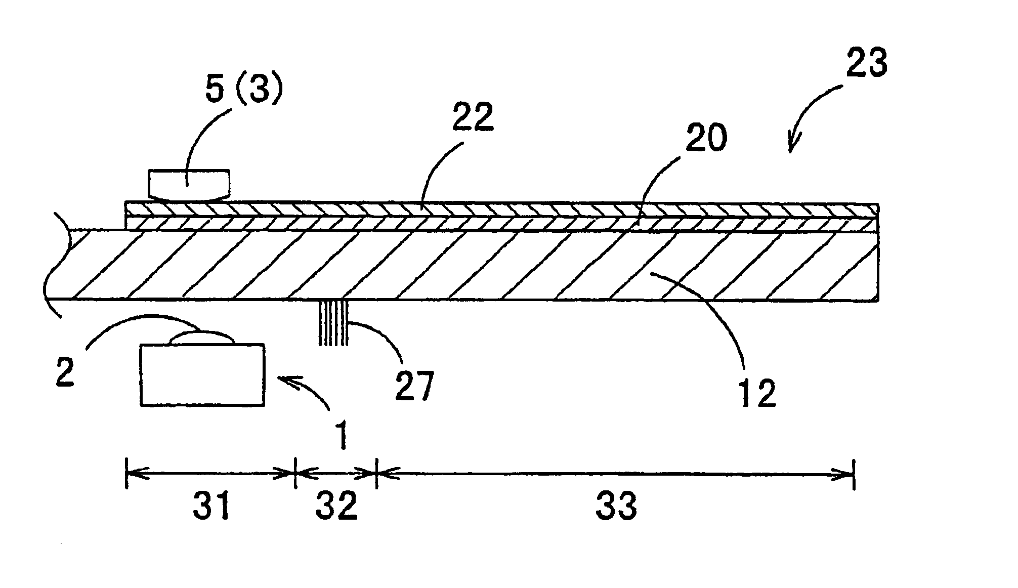
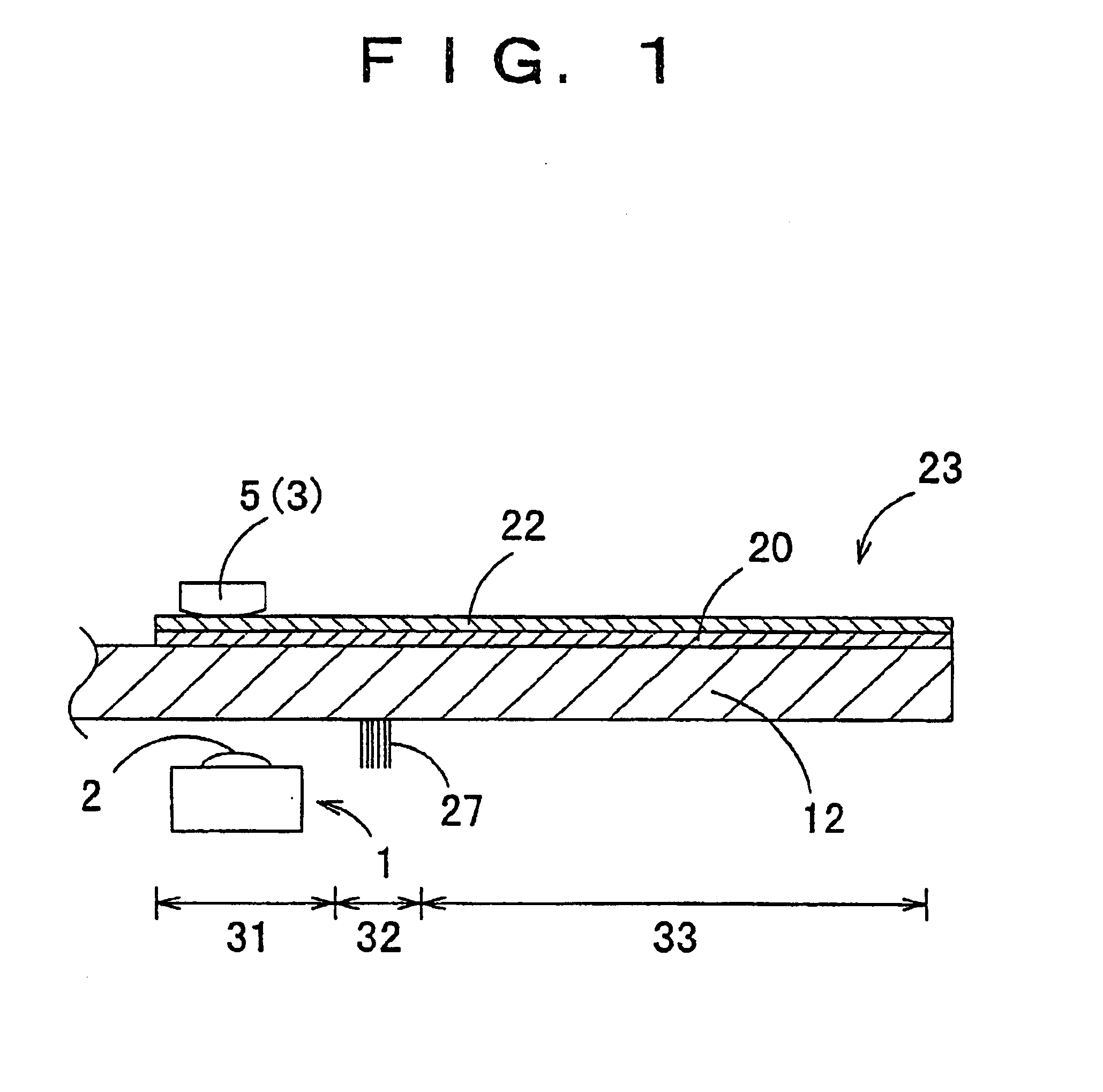
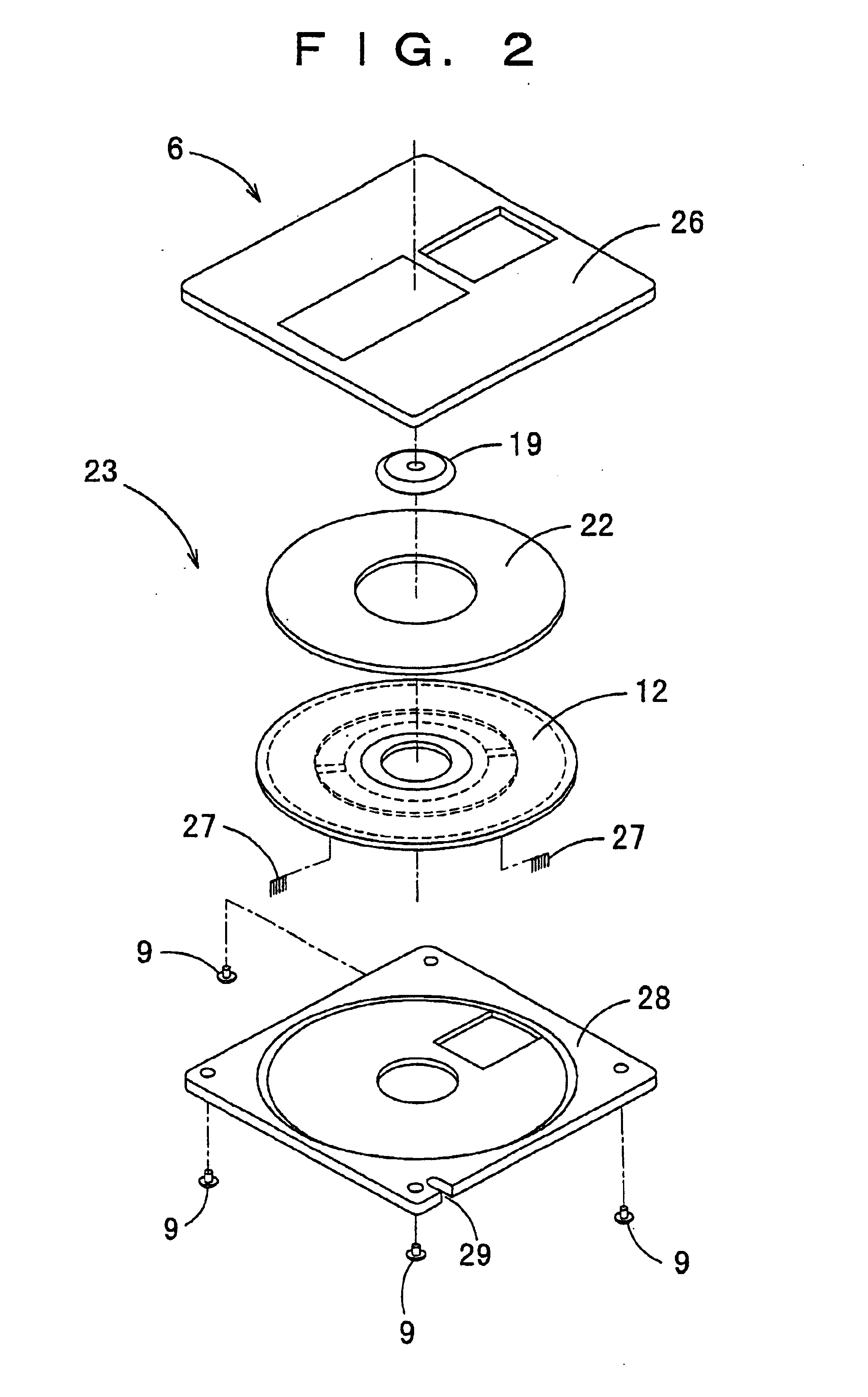
[0092]FIG. 1 is a sectional view showing the major portions of a cleaning disk and a magneto-optical disk drive apparatus in accordance with a first embodiment of the present invention in a state of cleaning. FIG. 2 is an exploded perspective view showing the cleaning disk. FIG. 3 is an exploded perspective view showing the cleaning disk and the magneto-optical disk drive apparatus. FIG. 4 is a sectional view showing the major portions of a magneto-optical disk for ordinary recording. FIG. 5 is an explanatory view showing operation for recording on the cleaning disk.

[0093]In FIGS. 1 to 5, an optical head 1 is provided with an objective lens 2 for gathering and applying laser light to a magneto-optical disk 4 or a cleaning disk 23.

[0094]The objective lens 2 is driven by an objective lens drive apparatus (not shown), for example, on two axes by virtue of electromagnetic drive so that an optical spot follows surface wobbling and eccentricity of the magneto-optical disk 4 or the cleanin...

second embodiment

[0115]FIG. 6 is a sectional view showing the major portions of a cleaning disk and a magneto-optical disk drive apparatus in accordance with a second embodiment of the present invention in a state of cleaning, and FIG. 7 is an exploded perspective view showing the cleaning disk and the magneto-optical disk drive apparatus.

[0116]Referring to FIGS. 6 and 7, this embodiment differs from the first embodiment in that information regarding magnetic head drive current (a current value) and information regarding disk rotation speed (a value representing rotation speed) at the time when the cleaning disk is used have been recorded in the disk information area 34 of a cleaning disk 30 in advance.

[0117]Next, operation will be described. In cleaning operation, when the cleaning disk 30 is loaded into the magneto-optical disk drive apparatus, the optical head 1 first reads the disk information area 34. In this disk information area 34, the information regarding the magnitude of a modulated curre...

third embodiment

[0123]FIG. 8 is a sectional view showing the major portions of a cleaning disk and a magneto-optical disk drive apparatus in accordance with a third embodiment of the present invention in a state of cleaning.

[0124]Referring to FIG. 8, this embodiment differs from the first and second embodiments in that, in the disk information area 44 of a cleaning disk 40, information (an output power value) regarding the laser power of the optical head 1 at the time when the cleaning disk is used has been recorded in advance.

[0125]Next, operation will be described. In cleaning operation, when the cleaning disk 40 is loaded into the magneto-optical disk drive apparatus, the optical head 1 first reads the disk information area 44. In this disk information area 44, the setting information of the power of laser emitted from the optical head 1 in the case when the cleaning disk 40 is used has been recorded in advance; the signal read by the optical head 1 is sent to an optical head drive circuit 47 as...


PUM

PropertyMeasurementUnit
thicknessaaaaaaaaaa
thicknessaaaaaaaaaa
currentaaaaaaaaaa

Abstract

The present invention provides a cleaning disk and a magneto-optical disk drive apparatus being simple in structure, adaptable to cleaning disks having various specifications, low in power consumption, low in electromagnetic noise, and preventing damage to the magnetic head and the optical head; the cleaning disk comprises a magneto-optical disk having an information layer, and a head-cleaning member, provided on the magneto-optical disk, for cleaning the magnetic head of the magneto-optical disk drive apparatus, wherein information regarding a magnetic head cleaning condition for setting the operation condition of the magneto-optical disk drive apparatus during cleaning of the magnetic head has been recorded in advance on the information layer of the magneto-optical disk. The magneto-optical disk drive apparatus reads the information regarding the magnetic head cleaning condition so as to set the operation condition properly.

Description

[0001]This application is a Divisional Application of S / N 09 / 889,017, filed Jul. 10, 2001 and now is U.S. Pat. No. 6,711,102 which is a 371 of PCT / JP00 / 08190 filed Nov. 20, 2000.TECHNICAL FIELD[0002]The present invention relates to a cleaning disk and a magneto-optical disk drive apparatus for removing dirt, dust and other foreign particles stuck to the magnetic head and optical head of an information recording / reproduction apparatus.[0003]Furthermore, the present invention relates to a recording / reproduction apparatus, such as a floppy disk drive (hereafter simply referred to as an FDD), a minidisk apparatus (hereafter simply referred to as an MD apparatus) and a magneto-optical data file apparatus, provided with a sliding contact type magnetic head to apply a modulated magnetic field to a recording medium. More particularly, the present invention relates to a recording / reproduction apparatus capable of carrying out recording and reproduction on both types of disk media, that is, a...

Claims


Application Information

Patent Timeline
Patent Type & Authority Patents(United States)
IPC IPC(8): G11B5/41G11B7/12G11B11/105G11B19/12G11B19/26
CPCG11B5/41G11B7/121G11B11/10584G11B11/10595G11B19/12G11B19/26G11B11/10532
Inventor MURAKAMI, YUTAKAMIZUNO, OSAMUNAKATA, HIDEKINAKAMURA, TOHRU
Owner PANASONIC CORP
Why Eureka
Try Eureka