Apparatus and method for conditioning a bowling lane using precision delivery injectors

a technology of injectors and bowling lane, which is applied in the direction of instruments, photosensitive materials, ways, etc., can solve the problems of difficult to precisely control the amount of dressing fluid application along the length of the bowling lane, difficult to control the precise amount of fluid transferred onto the lane, and virtually obsolete wick technology for today's lane conditioning needs

Active Publication Date: 2006-03-21
BRUNSWICK BOWLING PROD
View PDF92 Cites 9 Cited by
  • Summary
  • Abstract
  • Description
  • Claims
  • Application Information

AI Technical Summary

Benefits of technology

[0011]The invention solves the problems and overcomes the drawbacks and deficiencies of the prior art bowling lane conditioning systems by providing a bowling lane conditioning system, hereinafter designated “lane conditioning system”, which is versatile and robust, and which can provide a consumer with the ability to automatically and precisely control the thickness and layout of dressing fluid along the transverse and longitudinal dimensions of a bowling lane.
[0012]Thus an exemplary aspect of the present invention is to provide a lane conditioning system which provides a user the ability to accurately control dressing fluid resolution across the width of a bowling lane having thirty-nine (39) boards within a single board accuracy.
[0013]Another aspect of the present invention is to provide a lane conditioning system which provides an operator with the ability to select a lane conditioning pattern adjustable from two (2) units of dressing fluid up to ninety (90) units of dressing fluid within a resolution of one standard board (1 1 / 16″ segments across the width of the lane).

Problems solved by technology

The wick technology of the 1970's, 80's and early 90's however had exemplary limitations in that once the wick was disengaged from the transfer roller, a residual amount of fluid remaining on the transfer and buffer rollers would be applied onto the bowling lane, thus rendering it difficult to precisely control the amount of dressing fluid application along the length of the bowling lane.
Due to the inherent features of a wick which transfers fluid from a reservoir by means of the capillary action, wick technology made it difficult to control the precise amount of fluid transferred onto the lane and therefore the precise thickness and / or layout of the fluid along the transverse and longitudinal dimensions of the lane.
Additionally, changes in lane and bowling ball surfaces over the years created the need for higher conditioner volumes, higher viscosity conditioners and more accurate methods of applying conditioner to the lane / surface, thus rendering wick technology virtually obsolete for today's lane conditioning needs.
As with wick technology, metering valve technology had exemplary limitations in that even after flow of fluid had been stopped from being applied to the transfer roller, a residual amount of fluid remaining on the transfer roller, smoothing assembly 20 (as illustrated in U.S. Pat. No. 6,383,290, the disclosure of which is incorporated herein by reference), and the buffer would be applied onto the bowling lane, thus making it difficult to precisely control the amount of dressing fluid along the length of the bowling lane.
Because these technologies have less control in how the residual dressing fluid is transferred along the length of the lane, they often apply a second pass of dressing as the apparatus returns toward the front of the lane to achieve the desired conditioning pattern.
Compared to wick and metering pump technology, the apparatus of U.S. Pat. No. 5,679,162 had several additional unexpected drawbacks which required unreasonably high levels of maintenance of outlet slits 77, which tended to become clogged, for example, and adjustment of other associated components for adequate operation.

Method used


Image

  • Apparatus and method for conditioning a bowling lane using precision delivery injectors
  • Apparatus and method for conditioning a bowling lane using precision delivery injectors
  • Apparatus and method for conditioning a bowling lane using precision delivery injectors

Examples


first embodiment

[0105]lane conditioning system 100, which meets the aforementioned ABC and WIBC conditioning requirements, as well as conditioning requirements set forth in Europe and other countries, will now be described in detail.

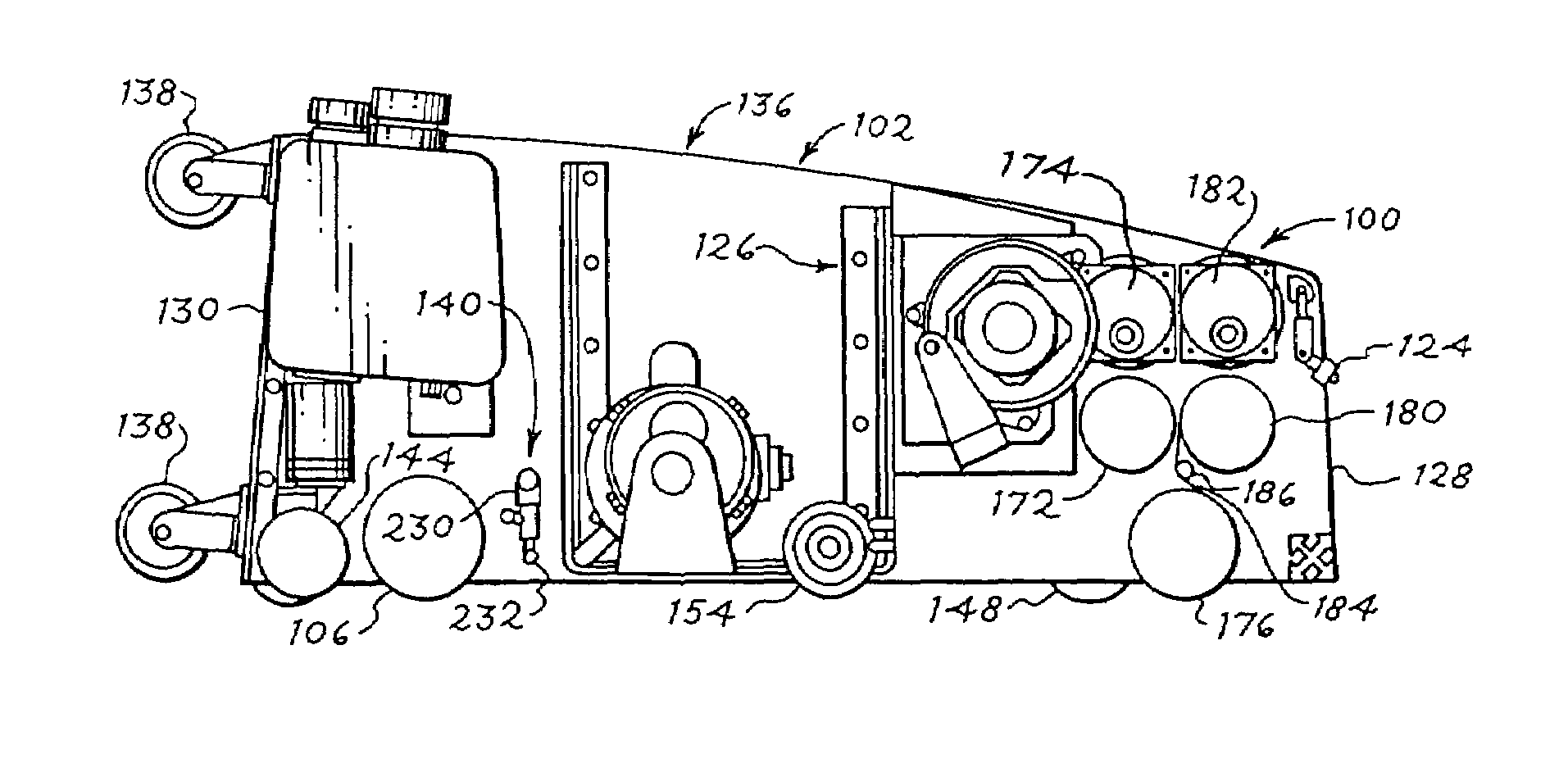
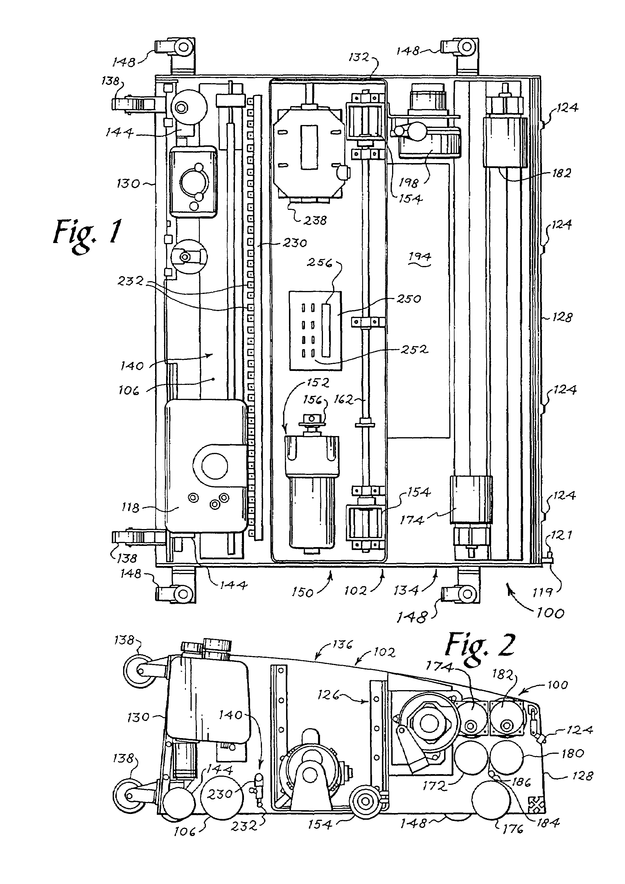
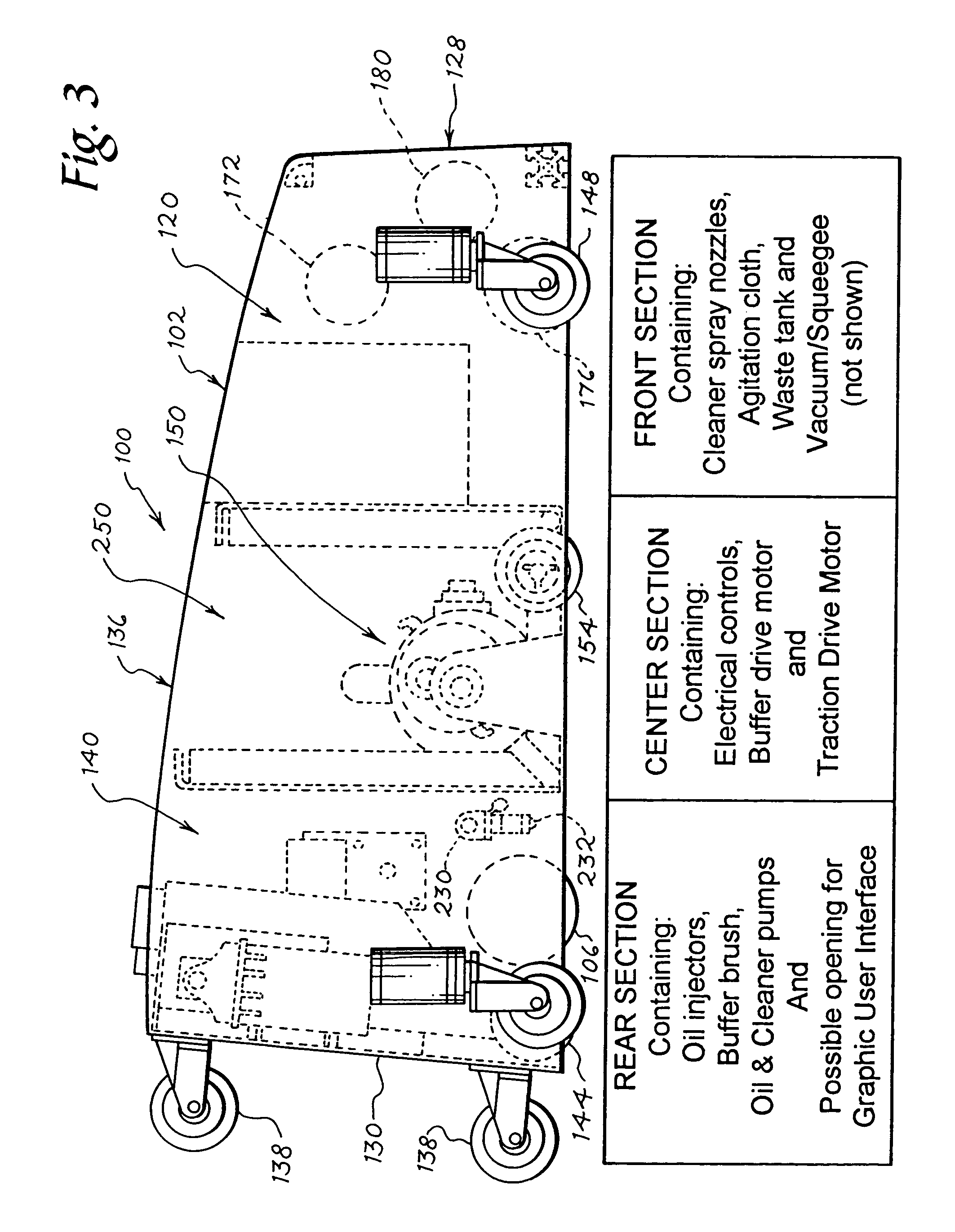
[0106]Referring to FIGS. 1–45 and 64–72 generally, and specifically to FIGS. 1–7, the first embodiment of lane conditioning system 100 broadly includes housing 102 including a cleaning fluid delivery and removal system 120, hereinafter designated “cleaning system 120”, dressing fluid delivery and application system 140, hereinafter designated “dressing application system 140”, drive system 150 and control system 250. Cleaning system 120 may broadly include cleaning fluid reservoir 122, telescoping cleaning fluid delivery nozzles 124 and vacuum system 126 for removal of cleaning fluid applied onto a bowling lane BL. Dressing application system 140 may broadly include precision delivery injectors 232 for injecting high viscosity lane dressing fluid directly onto bowling l...

second embodiment

[0138]lane conditioning system, generally designated 300 will now be described in detail in reference to FIGS. 1–7, 46A and 46B.

[0139]Referring to FIGS. 1–7, 46A and 46B, for the second embodiment of lane conditioning system 300, the cleaning system 120, vacuum system 126, drive system 150, and squeegee system 192 may be generally identical to the respective systems discussed above for lane conditioning system 100. For the second embodiment of lane conditioning system 300, for dressing application system 140, instead of thirty-nine (39) injectors 232 operatively connected to a reciprocating injector rail 230, twelve (12) precision delivery injectors 302 (similar to injectors 232), for example, may be provided with each of the injectors having a predetermined spacing of approximately 3.3 inches from centers. For the embodiment of FIGS. 46A and 46B, precision delivery injectors 302 may be positioned on an injector rail 304 and shuttled or otherwise reciprocated across the bowling lane...

third embodiment

[0141]lane conditioning system, generally designated 400 will now be described in detail in reference to FIGS. 1–7, 47 and 48.

[0142]Referring to FIGS. 1–7, 47 and 48, for the third embodiment of lane conditioning system 400, the cleaning system 120, vacuum system 126, drive system 150, and squeegee system 192 may be generally identical to the respective systems discussed above for lane conditioning system 100. For the third embodiment of lane conditioning system 400, for dressing application system 140, instead of injecting dressing fluid directly onto bowling lane BL, lane conditioning system 400 may include a dressing fluid transfer system 402 including a transfer roller 404 and buffer 406. Specifically, for the third embodiment, dressing fluid may be injected onto transfer roller 404 disposed in contact with buffer 406 and thereafter spread onto bowling lane BL by buffer 406. Transfer roller 404 may be operated by a separate transfer roller motor (not shown) or may instead be ope...


PUM


Abstract

The invention relates generally to the conditioning of bowling lanes, and, more particularly to an apparatus and method for automatically applying a predetermined pattern of dressing fluid along the transverse and longitudinal dimensions of a bowling lane.

Description

CROSS-REFERENCE TO RELATED APPLICATION[0001]This application claims the benefit of U.S. Provisional Application No. 60 / 500,222, filed Sep. 5, 2003, which is hereby incorporated by reference.BACKGROUND OF INVENTION[0002]a. Field of Invention[0003]The invention relates generally to the conditioning of bowling lanes, and, more particularly to an apparatus and method for automatically applying a predetermined pattern of dressing fluid along the transverse and longitudinal dimensions of a bowling lane.[0004]b. Description of Related Art[0005]It is well known in the bowling industry to clean and condition a bowling lane to protect the lane and to help create a predetermined lane dressing pattern for a desired ball reaction. Cleaning a bowling lane generally involves the application of a water-based or other cleaner, and the subsequent removal of the cleaner by means of an agitating material and / or vacuuming. While subtle variations may exist in the cleaning methods utilized by the various...

Claims


Application Information

Patent Timeline
Patent Type & Authority Patents(United States)
IPC IPC(8): B05B3/00A47L11/02B05B13/02B05C1/08A47L5/38A47L11/03A47L11/18A47L11/40A63D1/00A63D5/10B05B1/04B05B1/14B05B1/30B05B13/00B05B15/06B05C1/06
CPCA47L11/03B05B15/069A47L11/4011A47L11/4036A47L11/4041A47L11/4044A47L11/4047A47L11/4088A63D1/00A63D5/10B05B1/14A47L11/185B05B1/04B05B1/3053B05B13/005B05B15/658A63D5/00
Inventor BUCKLEY, GEORGE W.BURKHOLDER, ROY A.DAVIS, RICHARD A.GONRING, STEVEN J.MEADE, MARK H.MITCHELL, PATRICK J.RECKNAGEL, TROY A.
Owner BRUNSWICK BOWLING PROD
Why Eureka
Try Eureka