Precision attitude control system for gimaled thruster

a technology of gimaled thrusters and attitude control systems, which is applied in the field of gimbaled thrusters, can solve the problems of exceeding the life capability of the mechanisms, unable to operate the chemical thrusters (e.g., reas) for attitude control,

Active Publication Date: 2006-03-09
LOCKHEED MARTIN CORP
View PDF9 Cites 10 Cited by
  • Summary
  • Abstract
  • Description
  • Claims
  • Application Information

AI Technical Summary

Benefits of technology

[0006] In one exemplary embodiment, a simple control arrangement is provided which uses both reaction wheel assemblies (RWAs) and gimbaled HCTs for attitude and momentum control. The RWAs provide attitude control and the gimbaled HCTs are used to adjust the total momentum of a spacecraft. The total momentum includes the RWA momentum and the

Problems solved by technology

While the HCT fires, fuel-efficient attitude control is required, so the firing of the chemical thrusters (e.g., REAs) for attitude control is not viable.
The draw

Method used


Image

  • Precision attitude control system for gimaled thruster
  • Precision attitude control system for gimaled thruster
  • Precision attitude control system for gimaled thruster

Examples


Embodiment Construction

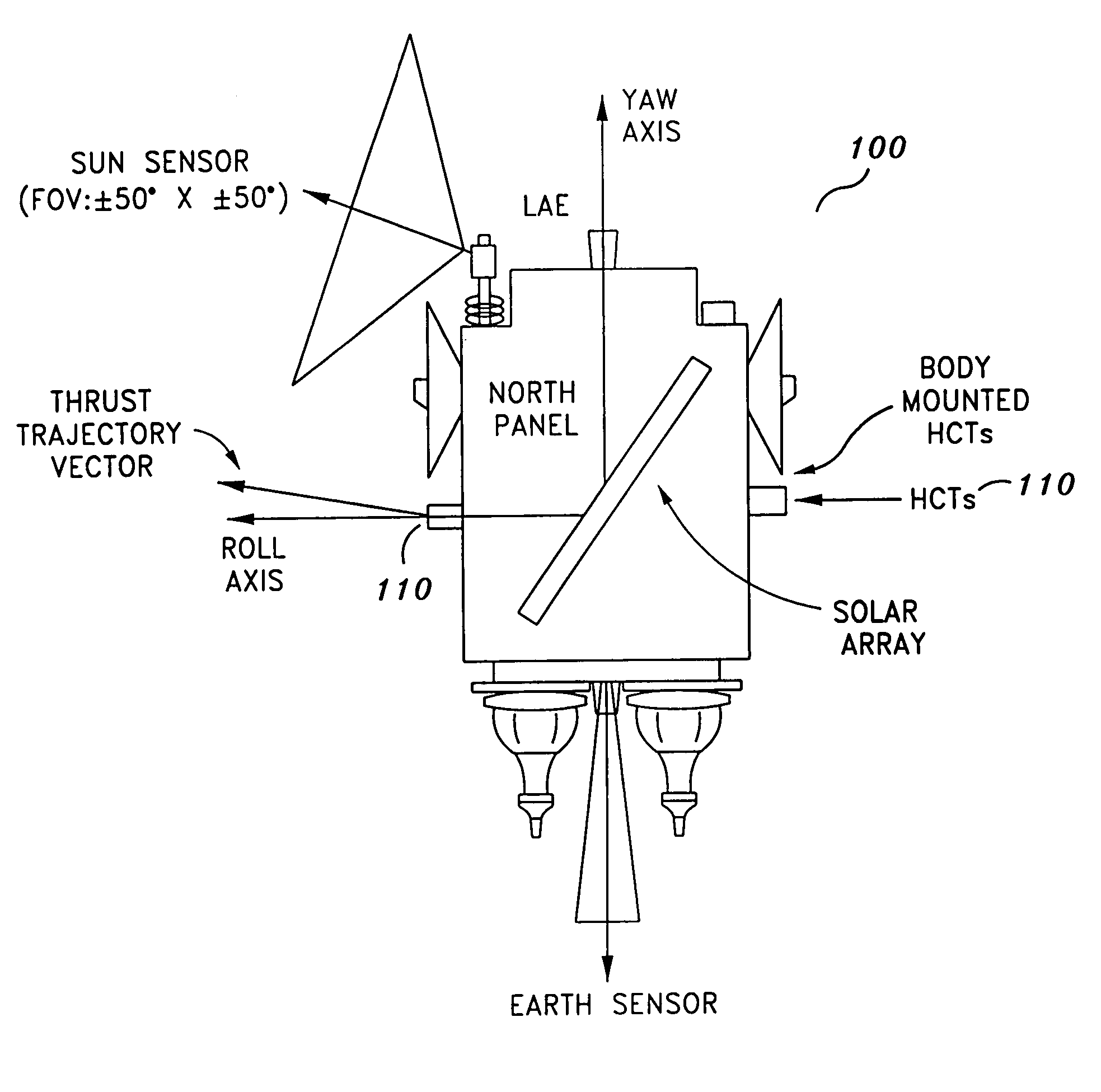
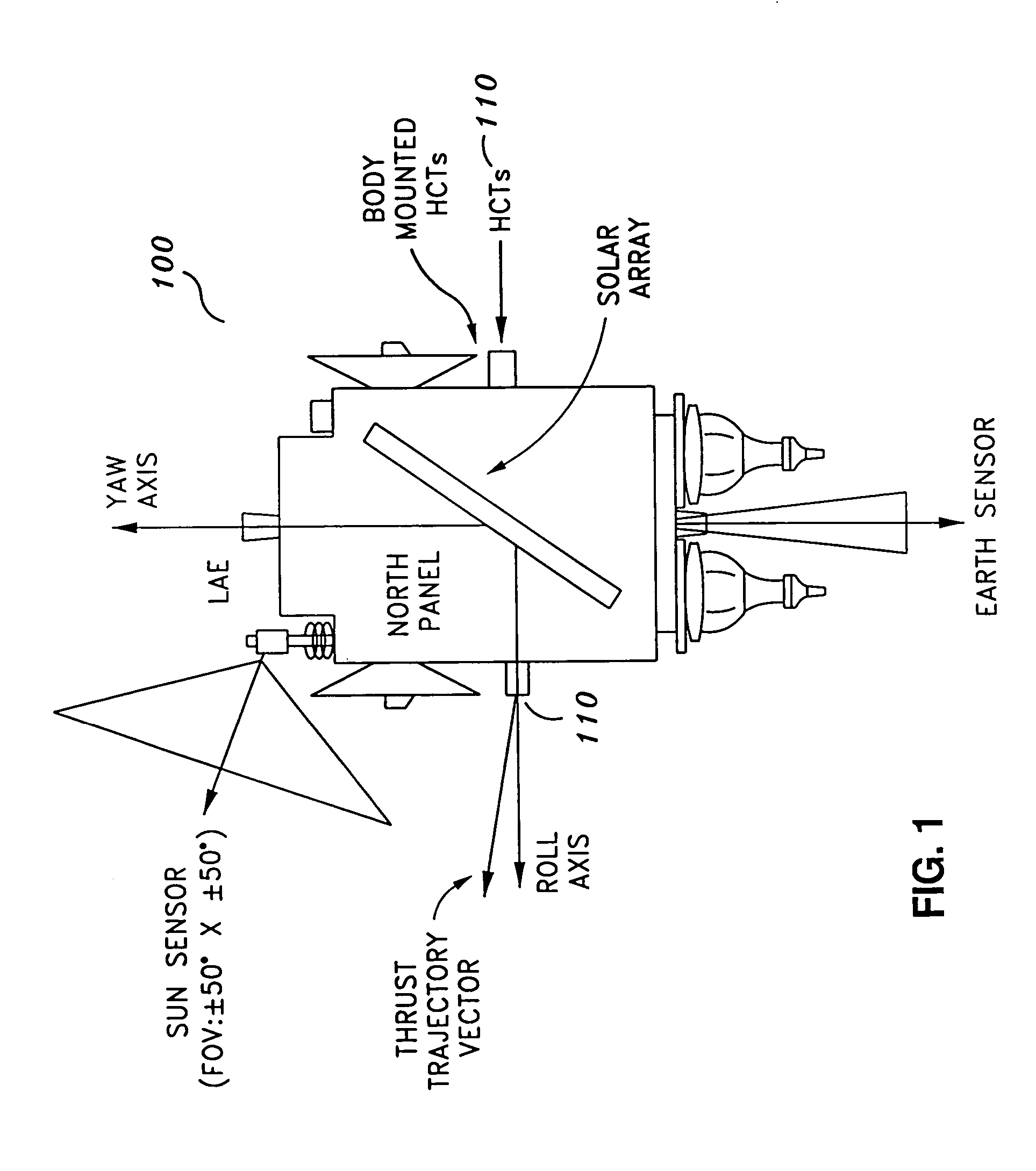
[0020] The present invention in the form of one or more exemplary embodiments will now be described. FIG. 1 illustrates one exemplary embodiment of the present invention. FIG. 1 shows a spacecraft 100 that includes a complement of four (4) HCTs each mounted on its own two-axis gimbaled platform. The spacecraft 100 includes a satellite and other types of space-based vehicles. HCTs 110 are mounted at the corner of the north and east faces and at the corner of the north and west faces. Two (2) more HCTs (not shown) are similarly mounted on the south side of the spacecraft 100. Based on the disclosure and teachings provided herein, a person of ordinary skill in the art will know of other possible HCT arrangements that can be used with the present invention. In an alternative arrangement, referred to as an “aft mounted” arrangement, four (4) HCTs are mounted on the aft end of the spacecraft (adjacent to the LAE (Liquid Apogee Engine) face or base panel), with two (2) HCTs mounted on a gi...


PUM


Abstract

A system for providing attitude control with respect to a spacecraft is provided. The system includes a reaction wheel control module configured to control a number of reaction wheel assemblies associated with the spacecraft in order to control attitude, and a maneuver control module configured to use a number of gimbaled Hall Current thrusters (HCTs) to control the total momentum associated with the spacecraft during an orbit transfer. The total momentum includes the momentum associated with the reaction wheel assemblies and the angular momentum of the spacecraft. Using the gimbaled HCTs to control the momentum associated with the reaction wheel assemblies during the orbit transfer results in minimal HCT gimbal stepping.

Description

CROSS-REFERENCES TO RELATED APPLICATION(S) [0001] The present application claims the benefit of priority under 35 U.S.C. § 119 from U.S. Provisional Patent Application Ser. No. 60 / 511,238, entitled “PRECISION ATTITUDE CONTROL SYSTEM FOR HALL CURRENT THRUSTER (HCT)”, filed on Oct. 14, 2003, the disclosure of which is hereby incorporated by reference in its entirety for all purposes.BACKGROUND OF THE INVENTION [0002] The present invention generally relates to gimbaled thrusters and more particularly to methods and systems for providing attitude and momentum control during gimbaled thruster firing for orbit transfer and stationkeeping maneuvers. [0003] Gimbaled thrusters (including Hall Current Thrusters (HCTs)) are used by spacecraft, such as military communications spacecraft, to perform partial orbit transfer. The HCTs, which are much more fuel-efficient than chemical thrusters, enable as much as 500 kg of additional payload to be delivered to the mission orbit. [0004] When used for...

Claims


Application Information

Patent Timeline
IPC IPC(8): B64G1/26B64GB64G1/00B64G1/28
CPCB64G1/007B64G2001/245B64G1/283B64G1/26B64G1/2427B64G1/245
Inventor PATEL, MOONISHRGOODZEIT, NEILE
Owner LOCKHEED MARTIN CORP
Why Eureka
Try Eureka