Single longitudinal mode diode laser module with external resonator

a diode laser module and diode laser technology, applied in the direction of laser details, instruments, optical elements, etc., can solve the problems of small variations and changes in the central wavelength that are not acceptable, difficult to execute automatic power control in a stable manner, and unsuitable for use in applications, etc., to achieve simple control arrangement, increase input current, and simple structure

Inactive Publication Date: 2015-04-30
SHOWA OPTRONICS
View PDF4 Cites 2 Cited by
  • Summary
  • Abstract
  • Description
  • Claims
  • Application Information

AI Technical Summary

Benefits of technology

[0016]According to the present invention, the laser diode which normally operates in a multi longitudinal mode can be operated in a single longitudinal mode by using a volume holographic grating so that the laser power may be allowed to increase monotonically with an increase in the input current. Therefore, the output laser power can be controlled at a constant level by automatic power control or by adjusting the input current while monitoring the laser power at any desired level of the laser power. Even when the laser diode may degenerate over time, and the levels of the input current (forward current) and the forward voltage required for a prescribed laser power output may vary, an optimum operating point can be maintained automatically at all times. Furthermore, these advantages can be gained by using a highly simple structure and a highly simple control arrangement.

Problems solved by technology

However, in the applications for analysis and measurement, even small variations and changes in the central wavelength are not acceptable in some cases, and single mode operation is essential, instead of multiple mode operation.
However, if the laser power does not increase monotonically with an increase in the input current, it is difficult to execute an automatic power control in a stable manner.
Superimposing high frequency current on the input current of the laser diode is an effective approach in applications where multi longitudinal mode operation creates no problem, but is not suitable for use in applications where single longitudinal mode operation is essential.

Method used


Image

  • Single longitudinal mode diode laser module with external resonator
  • Single longitudinal mode diode laser module with external resonator
  • Single longitudinal mode diode laser module with external resonator

Examples


first embodiment

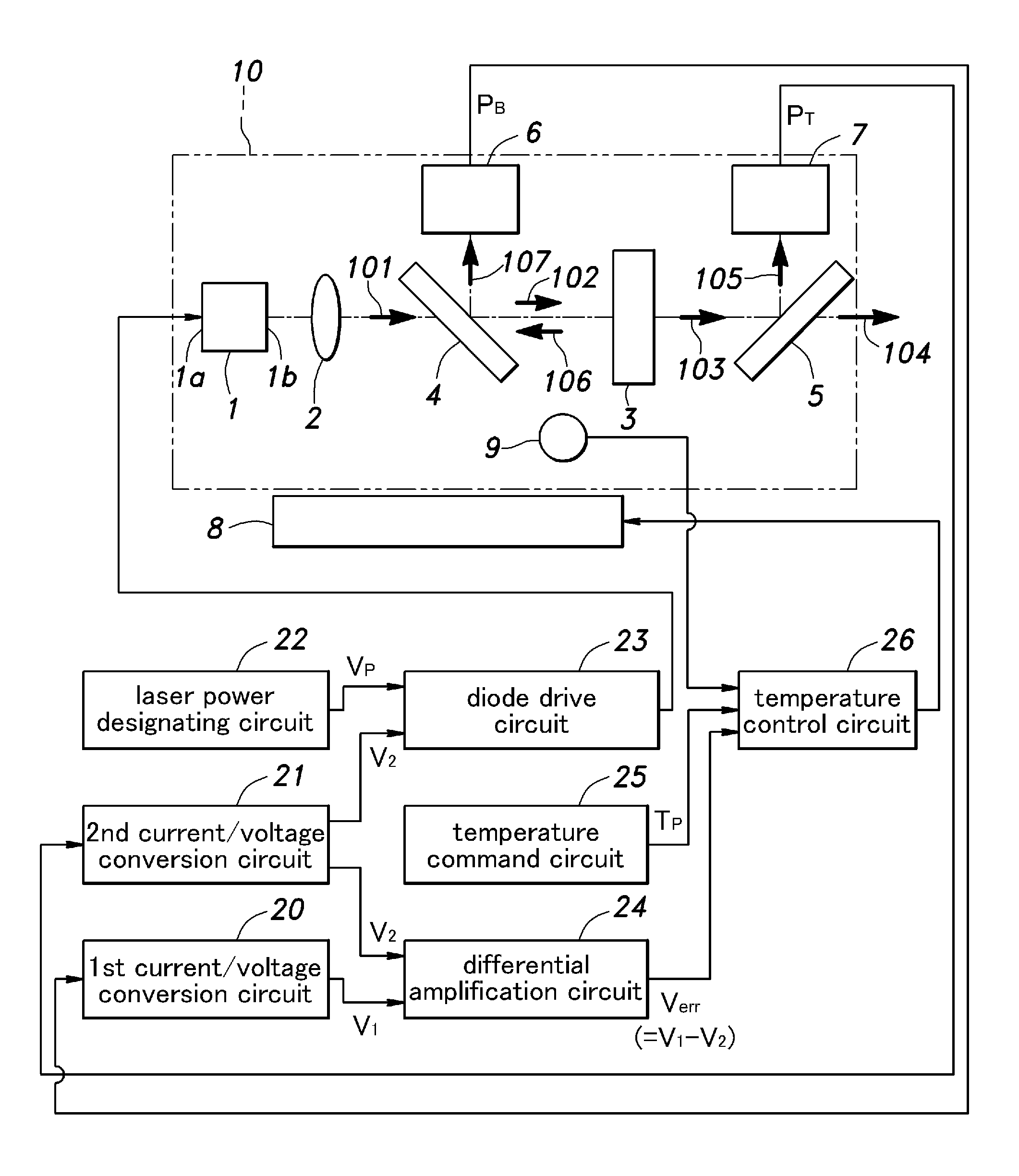
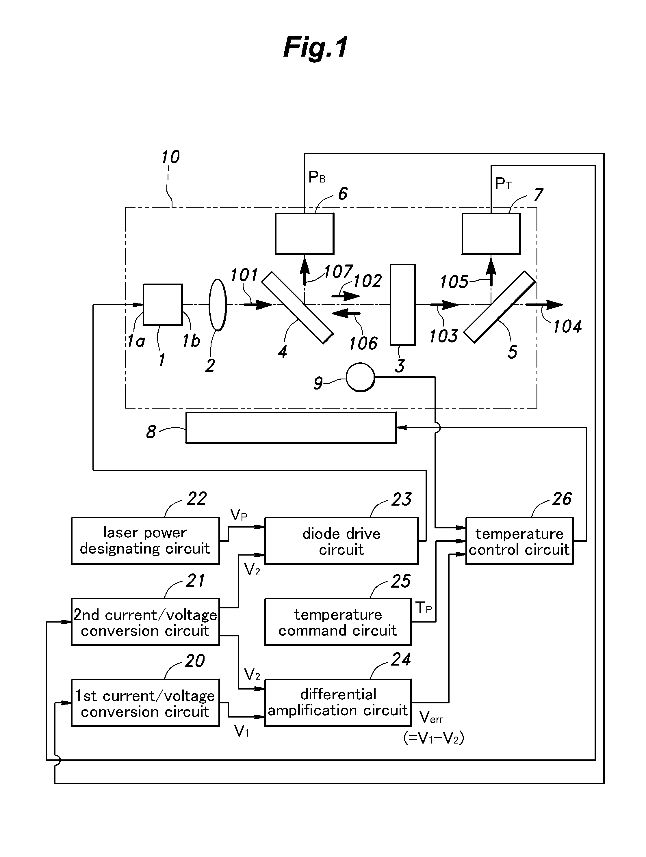
[0023]FIG. 1 shows both the optical system and the electronic system of a single longitudinal mode diode laser module provided with an external resonator according to the present invention.

[0024]A laser diode 1 consists of an InGaN diode having a gain peak wavelength of 405 nm. A first end 1a of an active layer of the laser diode 1 is provided with a high reflectance coating having a reflectance of 95% or higher for the wavelength of 405 nm, and the second end 1b thereof is provided with a low reflectance coating having a reflectance of 1% or less for the wavelength of 405 nm. When adequate electric current input is received, this laser diode 1 is able to emit laser light by itself without the aid of external optical devices. The laser diode 1, when operated by itself, operates under a mutli longitudinal mode, and the mode spacing in wavelength is given by the free spectral range which is determined by the resonator length of the laser diode 1. The value of the free spectral range o...

second embodiment

[0043]FIG. 5 shows a second embodiment of the single longitudinal mode diode laser module according to the present invention. In FIG. 5, the parts corresponding to those of the first embodiment are denoted with like numerals without necessarily repeating the description of such parts. The second embodiment is similar to the first embodiment in using a laser diode 1, a collimator lens 2, a volume holographic grating 3, a second beam splitter 5, a first light detector 6 and a second light detector 7, and these components are essentially the same as those of the first embodiment. However, the first beam splitter 4 is not used, and an anamorphic prism pair 13 consisting of a first prism 11 and a second prism 12 are used instead.

[0044]The cross sectional shape of the beam of the laser light 101 collimated by the collimator lens 2 is elliptic in shape, and the major axis / minor axis ratio of the ellipse is approximately 2. The anamorphic prism pair 13 reduces the beam of the laser light 10...

third embodiment

[0047]The optical arrangement of the third embodiment is identical to that of the first embodiment. The third embodiment includes a first current / voltage conversion circuit 20, a second current / voltage conversion circuit 21, a diode drive circuit 23 and a temperature control circuit 26 which are no different from the counterparts of the first embodiment. The third embodiment however does not include the laser power designating circuit 22, the differential amplification circuit 24 and the temperature designating circuit 25, and includes a microprocessor 27 that provides the functions of an analog-digital converter (ADC) and a digital-analog converter (DAC).

[0048]The laser power associated with the set voltage VP may be stored in the internal memory of the microprocessor 27, or may be given to the microprocessor 27 externally via a communication link (not shown in the drawings). This value (laser power) is produced from the DAC as the set voltage VP, and is forwarded to the diode driv...


PUM


Abstract

A single longitudinal mode diode laser module including a laser diode (1) and an external resonator using a volume holographic grating (3) having a prescribed reflective bandwidth is made amenable to automatic power control by controlling the temperature of the laser diode such that the laser power may be allowed to increase monotonically with an increase in the input current. Therefore, the output laser power can be controlled at a constant level by automatic power control or by adjusting the input current while monitoring the laser power at any desired level of the laser power.

Description

TECHNICAL FIELD[0001]The present invention relates to a diode laser module provided with an external resonator using a volume holographic grating (VHG) for controlling the wavelength.PRIOR ART[0002]Laser diodes that emit laser light by injection of electric current by using semiconductor as a gain medium are known to demonstrate wide variations in the central wavelength of the emitted laser light. The mass produced, commercially available laser diodes are typically given with a tolerance of ±3 nm to ±5 nm in the central wavelength. The central wavelength of a laser diode is also affected by the input current and the temperature.[0003]Some of the commercially available laser diodes with central wavelengths greater than 1 μm are configured to operate in a single longitudinal mode by providing a periodic structure near an active region of the waveguide structure, but a great majority of the commercially available laser diodes with central wavelengths less than 1 μm are configured to op...

Claims


Application Information

Patent Timeline
Patent Type & Authority Applications(United States)
IPC IPC(8): H01S5/00H01S5/024
CPCH01S5/024H01S5/005H01S5/02415H01S5/0683H01S5/06837H01S5/141H01S2301/163
Inventor KADOYA, MINORUOHARA, KENJI
Owner SHOWA OPTRONICS
Why Eureka
Try Eureka