Active sound muffler and active sound muffling method

Inactive Publication Date: 2008-04-01
KK TOSHIBA
View PDF13 Cites 3 Cited by
  • Summary
  • Abstract
  • Description
  • Claims
  • Application Information

AI Technical Summary

Benefits of technology

[0011]An object of the invention is to provide an active sound muffler that can reduce diffracted sounds by means of a relatively simple control arrangement if diffracted sounds are out of phase in the longitudinal direction of a sound insulating wall.
[0012]The present invention may provide an active sound muffler for reducing a sound to be reduced as emitted from a sound source located at one of the opposite sides of a sound insulating wall and diffracted and transmitted to the other side, the muffler comprising:
[0015]an additional sound source control means for controlling the output of the additional sound source so as to minimize the sound pressure or the acoustic intensity, whichever appropriate, based on the outcome of gauging of the sound source gauging device;

Problems solved by technology

Known active sound mufflers using loudspeakers operating as point sound sources are accompanied by a problem as described below.

Method used


Image

  • Active sound muffler and active sound muffling method
  • Active sound muffler and active sound muffling method
  • Active sound muffler and active sound muffling method

Examples


first embodiment

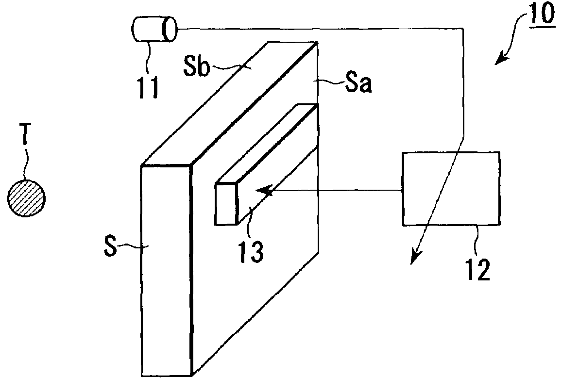
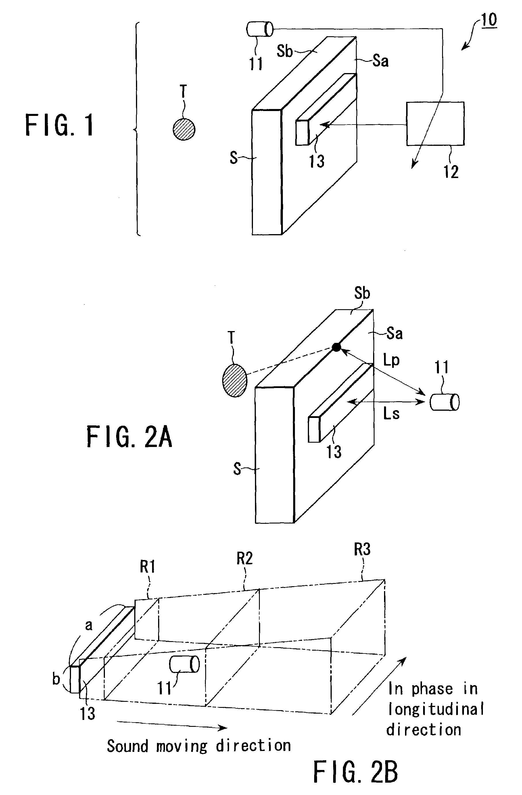
[0030]FIG. 1 is an illustration showing the configuration of active sound muffler 10 according to the invention. FIGS. 2A and 2B are illustrations showing the control principle of the control loudspeaker 13 that is incorporated in the active sound muffler 10. In FIG. 1, reference symbol T denotes a noise source and reference symbol S denotes a sound insulating wall. The noise source T may be a vehicle that may typically be a sedan. The sound insulating wall S is arranged near a road (not shown) on which the vehicle, or the noise source, passes in order to separate the road side and the side where sounds are to be muffled. The longitudinal direction of the wall S is arranged along the road.

[0031]The active sound muffler 10 comprises a control microphone (sound source gauging device) 11, a control circuit (additional sound source control means) 12 and a control loudspeaker (additional sound source) 13. The control microphone 11 is arranged above the sound insulating wall S at a given ...

second embodiment

[0117]FIG. 12 is a schematic illustration of the configuration of active sound muffler 20 according to the invention. In FIG. 12, the components that are same as those of FIG. 1 are denoted respectively by the same reference symbols and will not be described any further.

[0118]The active sound muffler 20 comprises a control microphone (sound source gauging device) 11 arranged above the sound insulating wall S at a given position, which will be described hereinafter, in order to detect the sound pressure or the acoustic intensity of diffracted sound, a control circuit 21 for generating a sound with a phase inverse to that of the diffracted sound from a control loudspeaker 13, which will be described hereinafter, in order to minimize the signal detected by the control microphone 11 based on the output of the control microphone 11, the control loudspeaker (additional sound source) 13 fitted near the top end Sa of the side where sounds are to be muffled of the sound insulating wall S and...

third embodiment

[0124]FIG. 13 is a schematic illustration of the configuration of active sound muffler 30 according to the invention. In FIG. 13, the components that are same as those of FIG. 1 are denoted respectively by the same reference symbols and will not be described any further.

[0125]The active sound muffler 30 comprises a control microphone (sound source gauging device) 11 arranged in front of the control loudspeaker 13 of the sound insulating wall S at a given position, which will be described hereinafter, in order to detect the sound pressure or the acoustic intensity of diffracted sound, a control circuit 12 for generating a sound with a phase inverse to that of the diffracted sound from a control loudspeaker 13, which will be described hereinafter, in order to minimize the signal detected by the control microphone 11 based on the output of the control microphone 11 and the control loudspeaker (additional sound source) 13 fitted to the lateral surface Sa of the side where sounds are to ...


PUM


Abstract

An active sound muffler for reducing a sound to be reduced as emitted from a sound source located at one of the opposite sides of a sound insulating wall and diffracted and transmitted to the other side, the muffler comprises a control loudspeaker arranged at the front end or the other side of the sound insulating wall and adapted to output a control sound with a predetermined amplitude and a predetermined phase, a control microphone arranged above the sound insulating wall and adapted to gauge the sound pressure or the acoustic intensity of the sound to be reduced and that of the control sound and a control circuit for controlling the output of the control loudspeaker so as to minimize the sound pressure or the acoustic intensity, whichever appropriate, based on the outcome of gauging of the control microphone, and the control loudspeaker showing a line sound source characteristic.

Description

CROSS-REFERENCE TO RELATED APPLICATIONS[0001]This application is based upon and claims the benefit of priority from the prior Japanese Patent Application No. 2002-097649, filed Mar. 29, 2002, the entire contents of which are incorporated herein by reference.BACKGROUND OF THE INVENTION[0002]1. Field of the Invention[0003]This invention relates to an active sound muffler for reducing noises that are diffracted to propagate by a sound insulating wall. More particularly, this invention relates to an active sound muffler that is effective for noises in which low frequency sounds are dominant.[0004]2. Description of the Related Art[0005]Sound insulating walls are built along certain trunk roads loaded with heavy traffic. The known noise reducing techniques using sound insulating walls are apparently classified into two categories. One is to insulate sounds simply by building a tall sound insulating wall along a road in order to block noises. The other is to provide a noise reducing device...

Claims


Application Information

Patent Timeline
IPC IPC(8): H03B29/00F01N1/06H04B15/00G10K11/178
CPCG10K11/1788G10K2210/118G10K2210/124G10K2210/128G10K2210/3214G10K2210/3224G10K11/17813G10K11/17857G10K11/17873G10K11/17881E01F8/00
Inventor ENAMITO, AKIHIKONISHIMURA, OSAMUSHIOYAMA, TSUTOMU
Owner KK TOSHIBA
Why Eureka
Try Eureka