Image projection system and a method of controlling a projected pointer

a projection system and projection point technology, applied in the field of image projection system and a control method can solve the problems of high cost of system operation, inability to easily change the position of the projection pointer of the presenter standing off the computer, and inability to conduct smooth presentation without close coordination

Inactive Publication Date: 2006-06-13
SEIKO EPSON CORP
View PDF35 Cites 16 Cited by
  • Summary
  • Abstract
  • Description
  • Claims
  • Application Information

AI Technical Summary

Benefits of technology

Enables seamless and stable remote control of the projected image, allowing presenters to easily manage cursor positions and projector settings without needing to physically interact with the computer, enhancing the convenience and efficiency of multimedia presentations.

Problems solved by technology

However, during the course of the presentation, the presenter who is standing off the computer cannot easily change the position of the cursor.
This is inconvenient.
Furthermore, a keyboard connected to the computer must be operated in order to perform functions regarding the liquid crystal projector display such as, page controlling, and this is also very inconvenient.
However, this type of system operation is costly, and a smooth presentation cannot be conducted without close coordination between the presenter and computer operator.

Method used


Image

  • Image projection system and a method of controlling a projected pointer
  • Image projection system and a method of controlling a projected pointer
  • Image projection system and a method of controlling a projected pointer

Examples


Embodiment Construction

[0099]Following is a description of the preferred embodiment of the present invention with reference to the attached drawings.

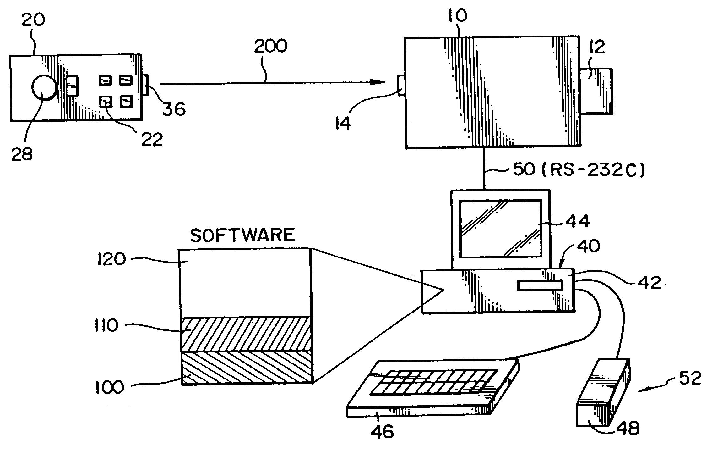
[0100]FIG. 1 shows an example of a configuration when a projecting means comprising a liquid crystal projector 10 is used to project a predetermined image from a projector output 12 to a desired display area, such as a screen 16. The liquid crystal projector 10 is constructed so as to enable connecting a plurality of video sources to the terminals thereof.

[0101]In the case of the present embodiment, two video sources can be connected. A first video source terminal allows connecting a video signal supplied from a computer, and a second video source terminal allows connecting a video playback device such as a video deck, video camera and video disk player. By selecting the video source, the video signal from the computer and video playback device can be selected and projected as a large size picture on the screen 16.

[0102]Although the basic operations of the li...


PUM

PropertyMeasurementUnit
areaaaaaaaaaaa
stabilityaaaaaaaaaa
circuit voltageaaaaaaaaaa

Abstract

The present invention relates to an image projection system whereby a display position of a pointer on a projected image can be easily controlled from a location separated from the main control means. The system comprises a liquid crystal projector, a personal computer for controlling the liquid crystal projector to display a pointer on a projected image in accordance with an operation signal from a main operating section and a predetermined program, and a remote controller for the liquid crystal projector.The remote controller comprises a pointing device and a light emitting portion for wirelessly transmitting an operation signal.The liquid crystal projector comprises a light receiving portion for receiving tirelessly transmitted signals. The personal computer controls the liquid crystal projector to transfer the received signals to the personal computer and further controls the display position of the pointer according to the transferred pointing device operation signals.

Description

[0001]This is a Continuation of application of prior pending application Ser. No. 10 / 315,012, filed Dec. 10, 2002; which is a continuation of application Ser. No. 09 / 548,346 filed Apr. 12, 2000, now U.S. Pat. No. 6,558,002, which in turn is a continuation of Application No. 09 / 084,399 filed May 27, 1998, now U.S. Pat. No. 6,186,630, which in turn is a divisional of application Ser. No. 08 / 573,520 filed Dec. 15, 1995, now U.S. Pat. No. 5,782,548. The entire disclosure of the prior applications is hereby incorporated by reference herein in its entirety.BACKGROUND OF THE INVENTION[0002]1. Field of the Invention[0003]The present invention relates to an image projection system and a method of controlling a projected pointer.[0004]2. Prior Art[0005]Multimedia presentation systems utilizing personal computers as the main control means are presently being developed and commercialized. As one example of such systems, a liquid crystal projector is controlled by a personal computer and the ima...

Claims


Application Information

Patent Timeline
Patent Type & AuthorityPatents(United States)
IPC IPC(8): G03B21/14G02F1/13G02B27/20G03B21/10G03B21/26G06F1/32G06F3/033G06F3/038G06F3/041H04B1/20H04N5/44H04N5/445H04N5/74H04N21/47H04Q9/00
CPCG03B21/26G06F1/3228G06F1/3259G06F3/033G06F3/038G06F3/041H04N5/4403H04N5/44582H04N9/3141G09G5/003G06F1/3203Y02B60/148G06F2203/0384H04B1/202H04N5/74H04N5/7441H04N21/47H04N2005/4432Y02B60/1253Y02B60/32H04N21/42206H04N21/42204Y02D10/00Y02D30/50
InventorMIYASHITA, KIYOSHI
OwnerSEIKO EPSON CORP