Model-based control for torque biasing system

a torque biasing and model-based control technology, applied in the direction of motor/generator/converter stopper, dynamo-electric converter control, instruments, etc., can solve the problems of difficult system accuracy, inability to easily measure, and inability to readily find torque sensors

Active Publication Date: 2006-09-05
NEW VENTURE GEAR INC
View PDF15 Cites 32 Cited by
  • Summary
  • Abstract
  • Description
  • Claims
  • Application Information

AI Technical Summary

Problems solved by technology

In the case where the specified system parameter is not directly measurable, system accuracy is difficult to achieve.
Torque biasing systems are typically controlled based on a parameter other than torque, because torque is not easily measurable and torque sensors are not readily available.
Torque sensors, however, would not be a total solution because the actual torque generated by a vehicle system is often much slower than is required by the biasing device.
As a result, conventional torque biasing systems are not controlled as accurately as is desired.

Method used


Image

  • Model-based control for torque biasing system
  • Model-based control for torque biasing system
  • Model-based control for torque biasing system

Examples


Embodiment Construction

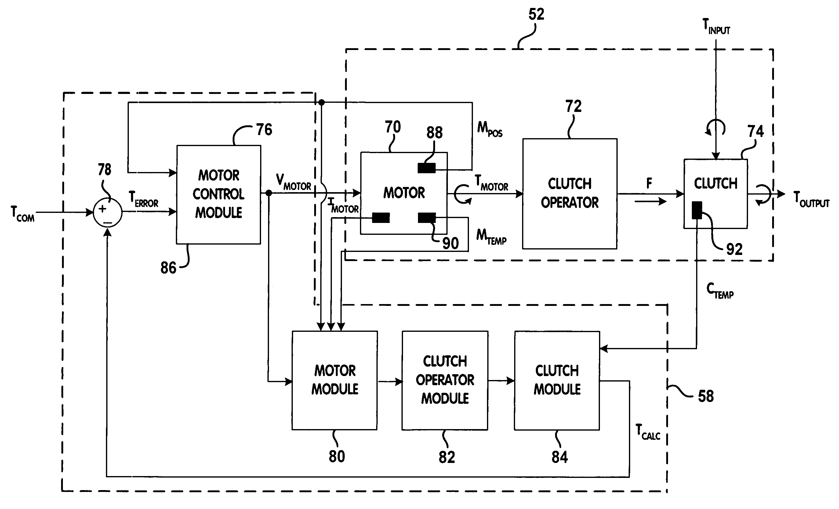
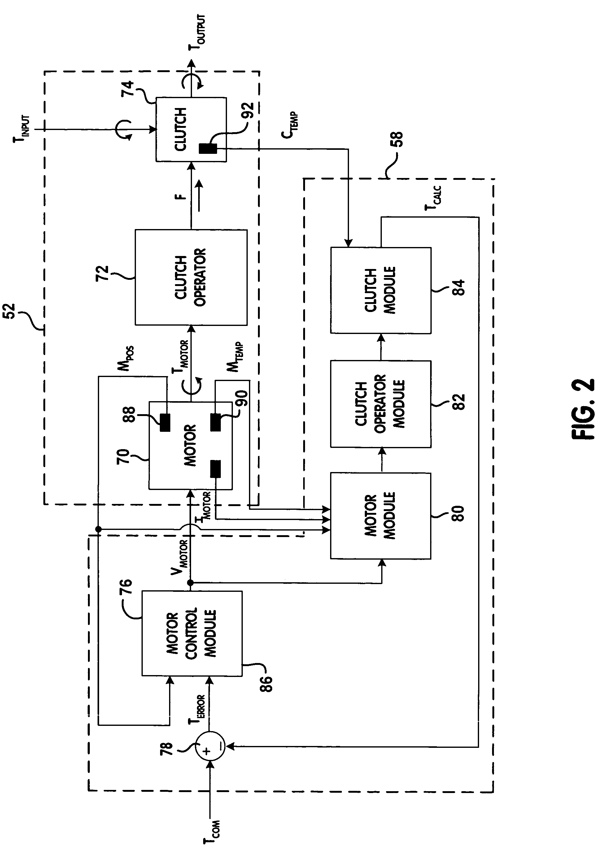
[0018]The following description of the preferred embodiments is merely exemplary in nature and is in no way intended to limit the invention, its application, or uses. As used herein, the term module refers to an application specific integrated circuit (ASIC), an electronic circuit, a processor (shared, dedicated, or group) and memory that execute one or more software or firmware programs, a combinational logic circuit, or other suitable components that provide the described functionality.

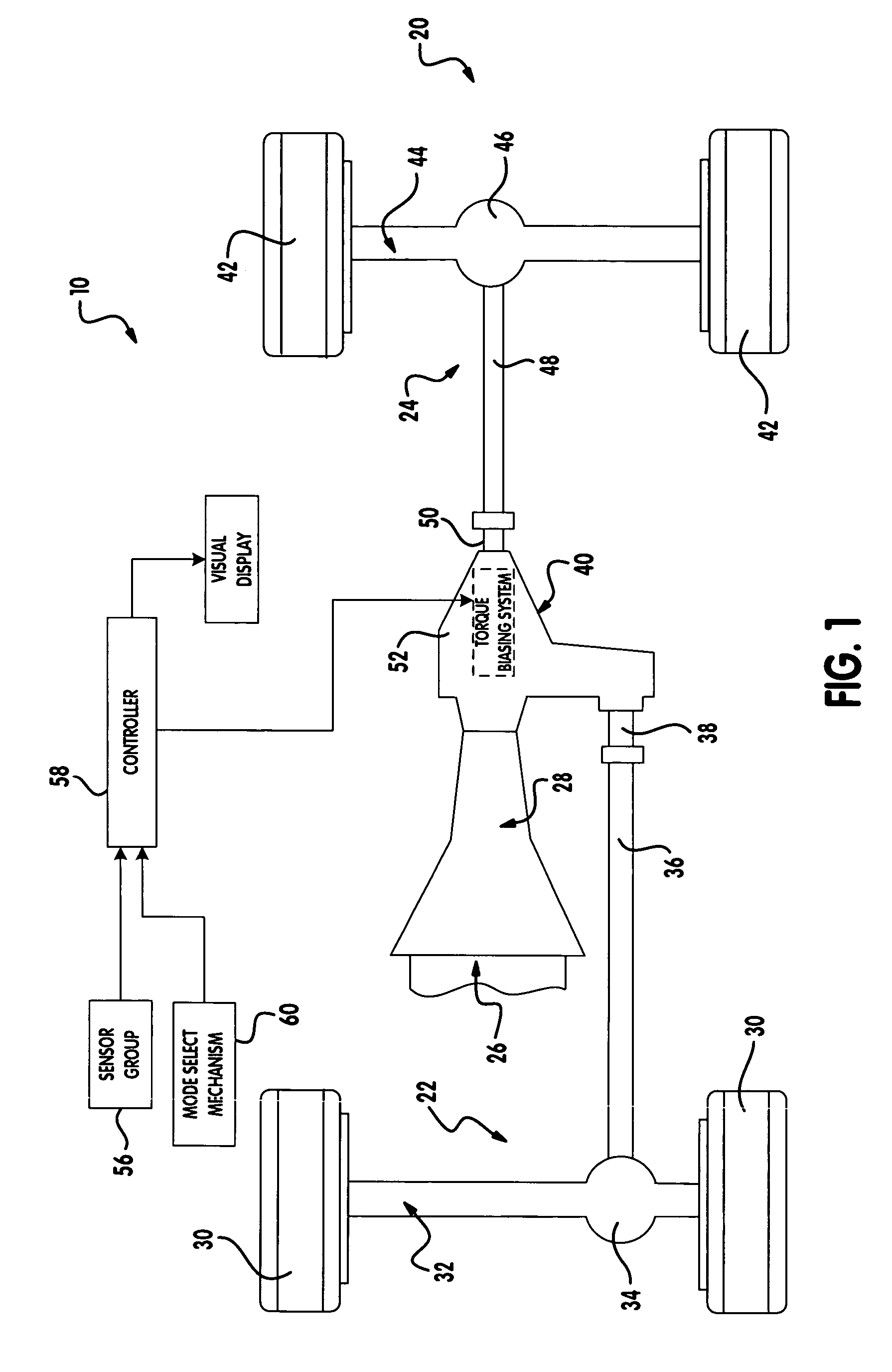
[0019]Referring now to FIG. 1, a four-wheel drive vehicle 10 is illustrated. The vehicle includes a front drive line 22, a rear drive line 24, and a power source, such as an engine 26 (partially shown), which provides drive torque to the front and rear drive lines through a transmission 28. The transmission 28 may be either a manual or automatic shifting type. The front drive line 22 includes a pair of front wheels 30 connected to opposite ends of a front axle assembly 32 having a front differential...


PUM


Abstract

A method of controlling a torque biasing system includes determining a torque command, calculating a torque error based on the torque command and a model-based torque. A control signal is generated based on the torque error and the torque biasing system is operated based on the control signal.

Description

FIELD OF THE INVENTION[0001]The present invention relates to torque biasing systems, and more particularly to model-based control of a torque biasing system.BACKGROUND OF THE INVENTION[0002]Torque biasing systems can be implemented in vehicle components including, but not limited to, a transfer case, a power take-off unit (PTU) and an axle. Torque biasing systems regulate torque transfer between an input and an output. More specifically, a clutch pack is operably disposed between the input and the output. The degree of engagement of the clutch pack is varied to regulate the amount of torque transferred from the input to the output. For example, when the clutch pack is disengaged, there is no torque transfer from the input to the output. When the clutch pack is fully engaged or locked, all of the torque is transferred from the input to the output. When partially engaged, a corresponding portion of the torque is transferred from the input to the output.[0003]The degree of clutch pack ...

Claims


Application Information

Patent Timeline
Patent Type & Authority Patents(United States)
IPC IPC(8): F16H59/64B60W10/02G05B5/00G06F7/00H02K17/32B60K23/08F16D48/06
CPCF16D48/06B60K23/0808F16D2500/3165F16D2500/50287F16D2500/70404Y10T477/75F16D2500/7082Y10T477/6395Y10T477/653Y10T477/753F16D2500/708
Inventor SMITH, WILLIAM E.BANSBACH, ERIC A
Owner NEW VENTURE GEAR INC
Why Eureka
Try Eureka