System and method for implementing a project facility

a project facility and project technology, applied in the field of system and method for implementing a project facility, can solve the problems of cumbersome tools b, >, and limited resources of embedded devices such as automobiles, medical devices, and cellular phones

Inactive Publication Date: 2006-09-19
WIND RIVER SYSTEMS
View PDF13 Cites 21 Cited by
  • Summary
  • Abstract
  • Description
  • Claims
  • Application Information

AI Technical Summary

Problems solved by technology

Embedded devices such as automobiles, medical devices, and cellular phones have limited resources compared to standard “desktop” PC-type computing environments (for example, less memory may be used and a limited set of I / O devices may be supported).
However, the tools 150 may be cumbersome in that the application has to be examined by a user of the IDE 1 in order to determine the components that the application needs, or does not need and thereafter, those needed components have to be manually added and the unneeded components have to be manually removed from the operating system 140.

Method used


Image

  • System and method for implementing a project facility
  • System and method for implementing a project facility
  • System and method for implementing a project facility

Examples


Embodiment Construction

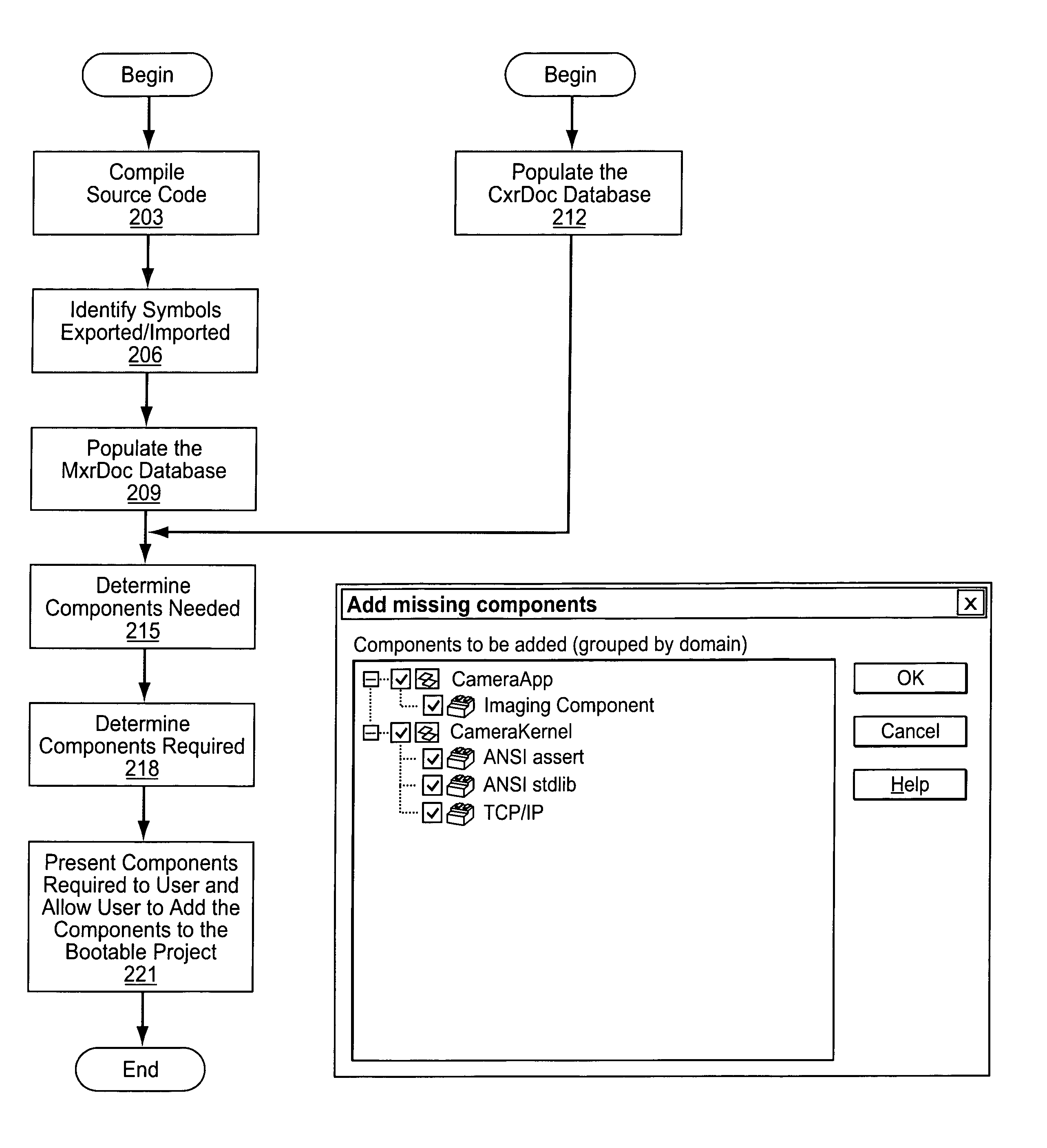
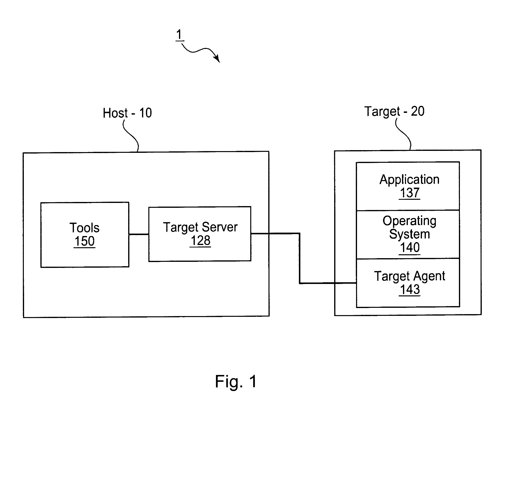
[0031]A first exemplary embodiment of an IDE according to the present invention includes a project facility (a tool residing on the host) that automatically determines if the application requires any components that are not included in the operating system 140 and allows a user of the project facility to add the required components to the operating system 140.

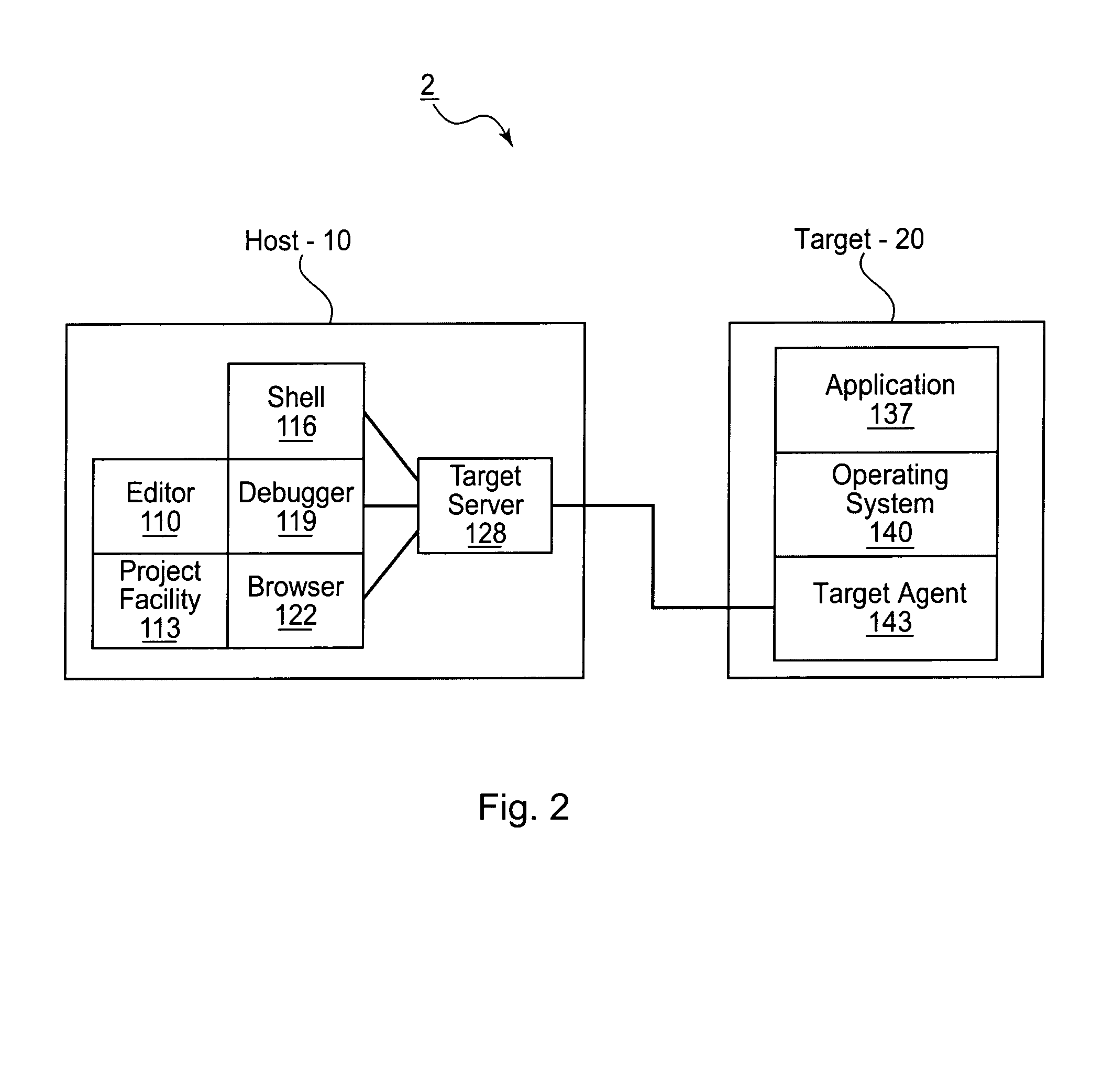
[0032]FIG. 2 shows a block diagram illustrating the first exemplary IDE 2. In FIG. 2, the host 10 may include a number of tools such as an editor 110 used to edit the source-code in which the application 137 is written. The host 10 may also include a project facility 113 that provides graphical and automated mechanisms for, among other things, creating applications that can be downloaded to the target 20, and for configuring the operating system 140 with selected components. For example, various networking and file system components may be required for one application and not another, and the project facility 113 provides a sim...


PUM


Abstract

A project analysis system and method is described to allow for automated generation of scalable bootable applications and downloadable applications, preferably in connection with an integrated development environment (IDE). The project analysis system and method includes facilities for automatically identifying and including software components in application development projects based on symbol dependencies and component dependencies. The project analysis system and method also includes facilities for automatically identifying and removing software components in application development projects where no symbol dependencies or component dependencies exist, thereby removing unused code. A graphical user interface is provided for user display and selection of includable and excludable components.

Description

CROSS REFERENCE TO RELATED APPLICATIONS[0001]This application claims the benefit of U.S. Provisional Application No. 60 / 184,856, filed Feb. 25, 2000.BACKGROUND INFORMATION[0002]Embedded devices such as automobiles, medical devices, and cellular phones have limited resources compared to standard “desktop” PC-type computing environments (for example, less memory may be used and a limited set of I / O devices may be supported). Because an embedded device has limited resources, it is easier to perform software development on an integrated development environment (“IDE”) prior to implementation in the embedded device.[0003]FIG. 1 shows a block diagram illustrating a typical IDE 1, such as the Tornado™ development environment from Wind River Systems, Inc., used to develop and debug software applications. The hardware used to implement the IDE 1 includes one or more hosts 10 and one or more targets 20 (e.g., embedded devices). The IDE 1 allows developers to organize, write, and compile appli...

Claims


Application Information

Patent Timeline
Patent Type & Authority Patents(United States)
IPC IPC(8): G06F9/44G06F7/00
CPCG06F8/20Y10S707/99948Y10S707/99945
Inventor LEVIEN, RICHARD B.MYERS, CY H.MOWERS, ANTHONY A.SCHILLE, CHRISTOPHER J.SHEPARD, MARC
Owner WIND RIVER SYSTEMS
Why Eureka
Try Eureka