Autoclave for curing retreaded tires

Active Publication Date: 2006-12-19
MICHELIN RECH & TECH SA
View PDF7 Cites 3 Cited by
  • Summary
  • Abstract
  • Description
  • Claims
  • Application Information

AI Technical Summary

Benefits of technology

[0005]According to the invention, heat transfer to the tires in a forced air flow autoclave is improved by increasing the air turbulence in the chamber, in particular, in the middle portion of the chamber. The inventors have theorized that the air flow through the chamber varies from a state of high turbulence where the air exits the return duct, to a smoother flow in the middle portion, followed by a more turbulent flow as the air is drawn from the chamber to the heat source. The smoother flow in the center portion is believed to be responsible for the less efficient heat transfer in this section of the chamber. The invention is accordingly directed to devices for disturbing the air flow in the chamber to increase turbulence.
[0006]A solution for generating turbulence in the air flow, according to the invention, is to direct or duct a portion of air from the supply duct into the chamber at approximately the center of the flow path in the chamber, which in a longitudinal chamber is approximately the longitudinal midpoint. The ducted air is directed to flow counter or cross to the flow of air in the chamber, and accordingly, generates turbulence in the chamber air flow. A simple ducting device is an aperture in the supply duct wall wi

Problems solved by technology

A problem in the art exists in chambers that circulate air between the chamber and the heat source.
Nonetheless, a “cold spot” can occur where the vulcanization reaction is less effective, between where the heated air enters the chamber from the supply duct and where the

Method used


Image

  • Autoclave for curing retreaded tires
  • Autoclave for curing retreaded tires
  • Autoclave for curing retreaded tires

Examples


Embodiment Construction

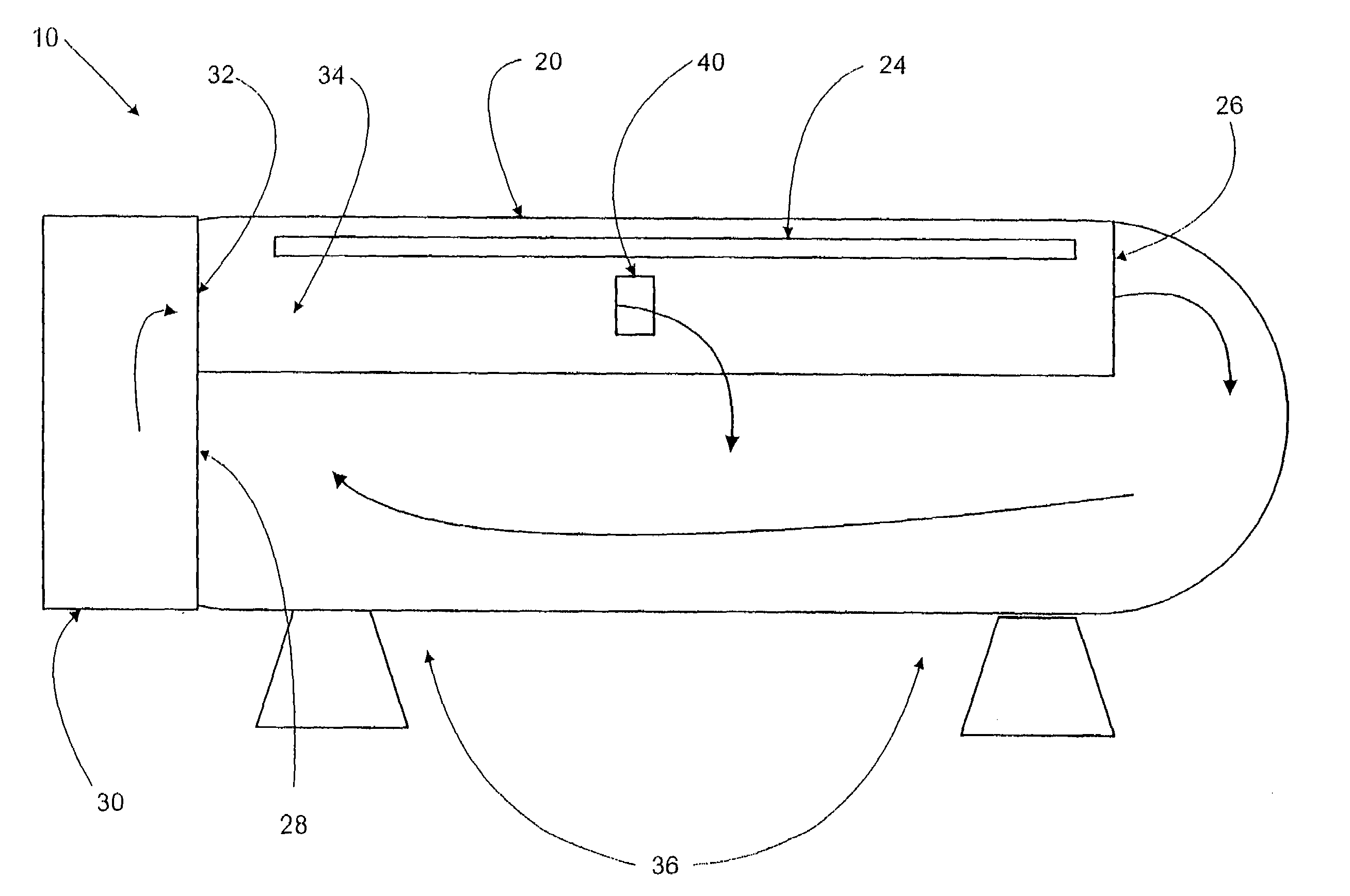
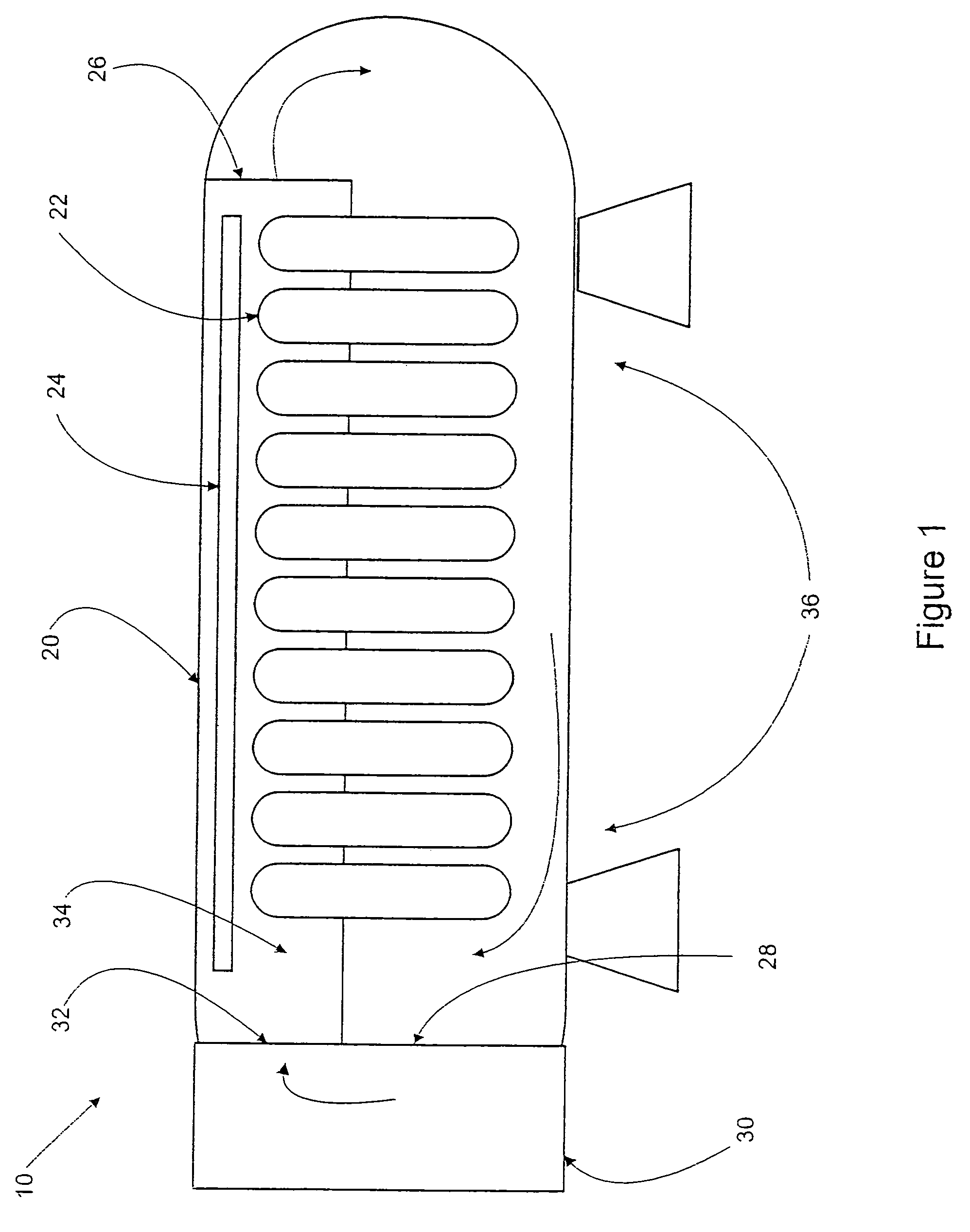
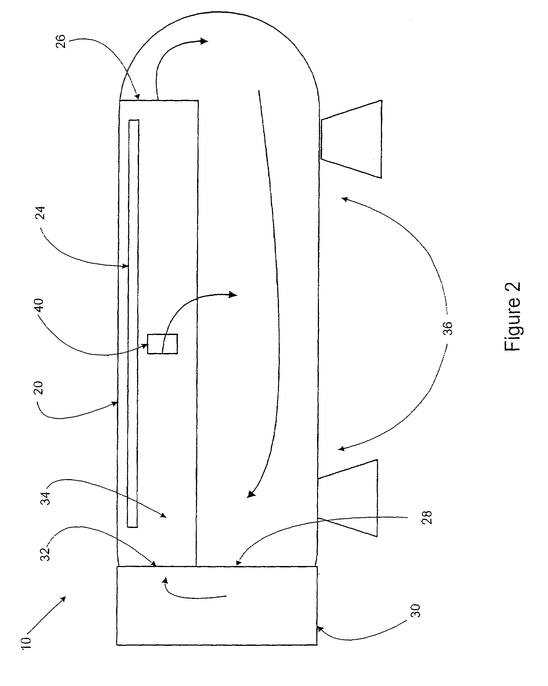
[0018]FIG. 1 is a simplified, schematic illustration of an autoclave 10 for curing retreaded tires currently in common use in the industry. The autoclave 10 includes an elongated chamber 20 providing a space for containing a plurality of tires 22 for a cure process. The tires 22 are suspended from a rack or frame 24 so that heated air may circulate freely about the tires. Typically the tires 22 are placed in envelopes or covers that are connected to a vacuum source (not shown) to evacuate the interior of the envelope, especially the region of the new tread and tire crown, to eliminate air at the bonding site and to generate a pressure differential between the chamber and the tread.

[0019]An autoclave of the type shown is used in the type of retread process in which a cured tread and an uncured gum rubber layer are placed on a prepared tire casing and the assembly is then heated under pressure to vulcanize the gum rubber, bonding the tread to the casing.

[0020]In the type of autoclave ...


PUM

PropertyMeasurementUnit
Flow rateaaaaaaaaaa

Abstract

An improved autoclave for curing retread tires includes a chamber with circulating air flow having turbulence generating devices located in a middle length-wise portion of the chamber. The turbulence generating devices include apertures to guide air from a supply duct into the chamber, and/or wedge-shaped elements or fins mounted on the interior wall of the chamber to disrupt the air flow and cause turbulence.

Description

BACKGROUND AND SUMMARY OF THE INVENTION[0001]The invention relates to autoclaves for curing retreaded tires, that is, heat and pressure chambers for vulcanizing a material bonding a new tread to a used tire casing. More particularly, the invention is directed to an improvement in the heat transfer characteristics of an autoclave operating with forced-air flow.[0002]A type of autoclave in current use in the retread industry includes a chamber having an elongated, cylindrical shape capable of containing a group of tires for a curing process. The tires are encased in flexible covers or envelopes, which are evacuated to remove air from between and around the new tread and tire casing. The tires in the envelopes are suspended in the chamber to allow heated air to flow to the outer circumference of the tire and tread. The air in the autoclave is pressurized to force the new tread against the tire casing to achieve a uniform, tight bond. The air is heated to a temperature sufficient to pro...

Claims


Application Information

Patent Timeline
IPC IPC(8): B29C35/02B29C35/04B29D30/54
CPCB29C35/0227B29C35/045B29D30/54B29C2035/046B29D2030/545B29L2030/00Y10S156/909
Inventor LAHMANN, JANLOUCHART, III, THEOPHILE HENRY
Owner MICHELIN RECH & TECH SA
Why Eureka
Try Eureka